The effects of mould growth on both the integrity of the tape and the recorded sound or image can be significant.
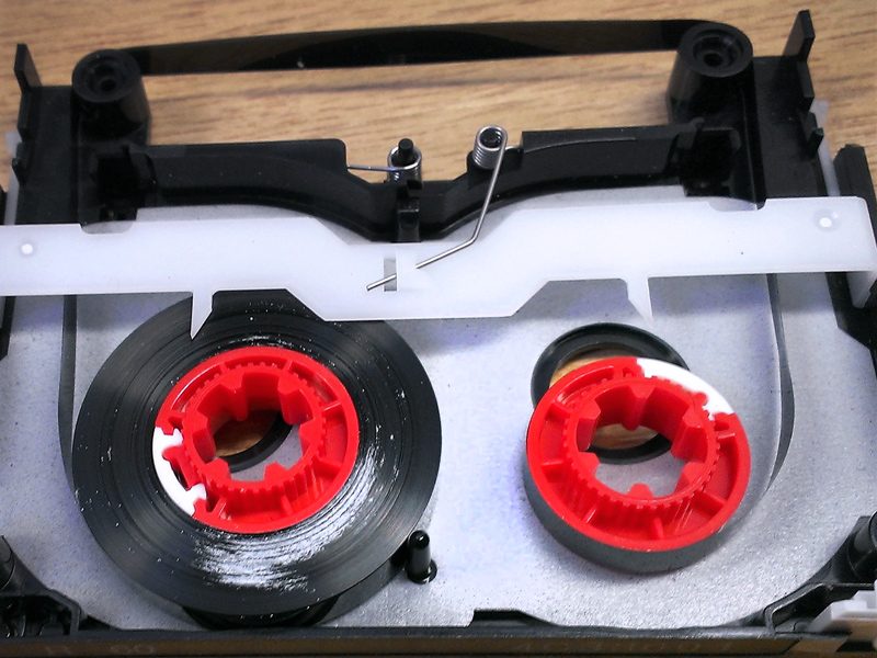
Mould growth often sticks the tape layers in a tightly packed reel together often at one edge. If an affected tape is wound or played this can rip the tape.
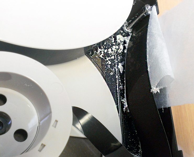
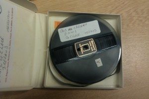
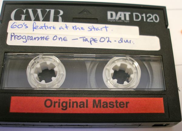
DAT audio cassette shell opened to reveal visible mould on edge of tape pack
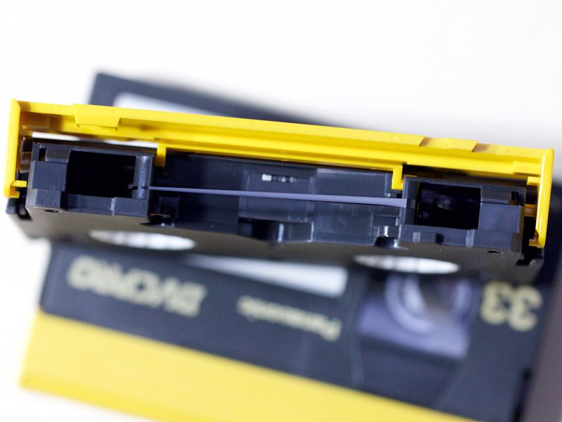
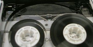
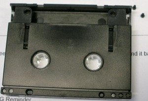
DVCPRO video cassette lid lifted to show tape split longitudinally
If the mould has damaged the record side of the tape then the magnetic tracks are usually damaged and signal loss will result. This will create audible and visual artefacts that cannot be resolved.
Mould develops on tapes that have been stored in less-than-optimum conditions. Institutional collections can exhibit mould growth if they have not have been stored in a suitable, temperature controlled environment. For magnetic tape collections this is recommended at 15 +/- 3° C and 40% maximum relative humidity, although the British Library's Preservation Advisory Centre suggest 'the necessary conditions for [mould] germination are generally: temperatures of 10-35ºC with optima of 20ºC and above [and] relative humidities greater than 70%.'
For domestic and personal collections the mouldy tapes we receive are often the ones that have been stored in the shed, loft or basement, so be sure to check the condition of anything you think may be at risk.
We do come across cases where mould is not easily visble to the naked eye without dismantling a cassette shell - so unless you can be sure your tape has been kept in optimum storage conditions for its entire 'life', it's better to err on the side of caution. Playing a mould-affected tape in a domestic machine can very easily damage the tape.
It is important to remember that a mouldy tape is a hazard not just for the individual tape. If not handled carefully it can potentially spread to other parts of your collection, so must be treated immediately.
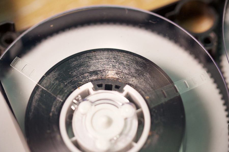
filaments of mould on Hi8 video tape edge
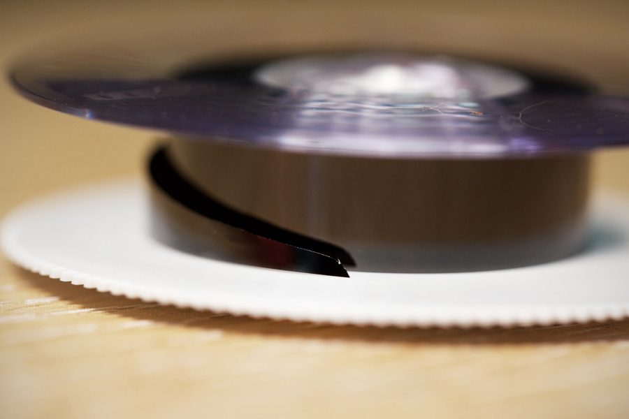
Hi8 tape showing longitudinal tear caused by sticking
There are several stages to our treatment of your mouldy tape.
Firstly, if the mould is still active it has to be driven into dormancy. You will be able to tell if there is active mould on your tape because it will be moist, smudging slightly if it is touched. If the tape is in this condition there is a high risk it will infect other parts of your collection. We strongly advise you to quarantine the tape (and of course wash your hands because active mould is nasty stuff).
When we receive mouldy tape we place it in a sealed bag filled with desiccating silica gel. The silica gel helps to absorb the tape's moisture and de-fertilises the mould's 'living environment'.
When the mould becomes dormant it will appear white and dusty, and is relatively easy to treat at this stage. We use brushes, vacuums with HEPA filters and cleaning solutions such as hydrogen peroxide to clean the tape.
Treatment should be conducted in a controlled environment using the appropriate health protections such as masks and gloves because mould can be very damaging for health.
All machines used to playback mouldy tape are cleaned thoroughly after use - even tapes with dormant mould still carry the risk of infection.
Most tapes-infested with mould are treatable and can be effectively played back following the appropriate treatment procedures. Occasionally mould growth is so extensive however that it damages the binder irreparably. Mould can also exacerbate other problems associated with impaired tape, such as binder hydrolysis.
gently dislodging mould from U-matic video tape
Edge and upper-surface mould causing U-matic video tape to stick
When it comes to tape mould the message is simple: it is a serious problem which poses a significant risk to the integrity of your collection.
If you do find mould on your tapes all is not lost. With careful, specialised treatment the material can be recovered. Action does need to be taken promptly however in order to salvage the tape and prevent the spread of further infection.
Feel free to contact us if you want to talk about your audio or video tapes that may need treatment or assessment.
The binder is crucial part of the composition of audio and video magnetic tape. It holds the iron oxide magnetisable coating on to its plastic carrier and facilitates its transport through the playback mechanism. It is also, however, 'universally agreed that with modern PET-based tape the binder is the weak link, and is generally the part of the tape which creates the most problems,' according to a UNESCO report.
There is of course no 'one-size-fits-all' answer to treating problems with tape binder. Each tape will have a unique manufacturing, playback and storage history that will shape its current condition, so restoration solutions need to respond on a case-by-case basis.
Detailed below are some of the common and diverse things that can go wrong with the tape binder, and how Greatbear can help restore your tape to a playable condition.
Binder Hydrolysis aka Sticky Shed Syndrome and Tape Baking
Probably the most well-known fault that can occur with magnetic tape is binder hydrolysis.
As its name indicates, hydrolysis is a chemical process caused by the absorption of water present in the tape's storage environment. In certain brands of tape, most notably Ampex, the binder polymers used in magnetic tape construction are broken apart as they react with water, which causes damage to the tape.
There are other theories about what happens when tapes get sticky and shed. Dietrich Schüller conducted interviews with experts of former tape manufacturers based in Germany, and concluded that 'the chemical recipe is the basis, if not the guarantee, for tape quality and stability. The production process, is equally, if not more essential.'
Schüller's research explains how the manufacture of tapes required a delicate balance between speed and precision, encompassing issues such as coating speed, proper dispersion of components, temperature and pressure of calendars. Professional tapes were produced at a rate between 100-200 metres per second (m/s). In the final stage of tape manufacture 'production speed reached 1000 m/s. This required the cross linking of binder components during the coating process.' This uneven distribution, Schüller found, sometimes led to sticky areas. [1]
Tapes exhibiting sticky shed syndrome will stick to the tape pack as they are unwound. These tapes are extremely vulnerable and need effective treatment before they can be played back. Playing a sticky tape is likely to damage the tape. It will also result in head clogs, stick-slip playback and seizure of the tape transport. In extreme cases the tape may fall apart entirely.
Although a serious problem, binder hydrolysis can be treated. Tape baking at controlled temperatures can temporarily improve binder integrity, helping to restore tape to a playable condition. In our studios we use a Thermo Scientific Heraeus B20 laboratory incubator for this process.
Lubricant Loss
Lubricants are a crucial part of the tape binder's composition, required to help the tape move smoothly through the transport. 'The quantity of lubricant is greater for video than for audio because of the higher writing and reading speeds.' [2]
Over time, the level of lubricant in the tape decreases because lubricants are partially consumed every time the tape is played. Lubricant levels decrease over time even if they are unplayed, particularly if they have not been stored in appropriate conditions for passive preservation.
As you will imagine, playing a tape back that has lost its lubricant carries with it certain risks. The tape may seize in the transport as a result of high friction, and the magnetic coating may be torn off the tape backing as it moves at a high speed past the tape head.
In cases where there is extreme lubricant loss we can apply a lubricant to help ease the tape through the transport. On the whole we are keen to use treatment methods that are as non-intrusive as possible, so such measures are kept to a minimum: 're-lubrication [...] must be seen very critically, as it is impossible to restrict added lubricants to the small amounts actually needed. Superfluous lubricants are difficult to remove from the tape guides, heads, and capstan and may interact with other tapes played on those machines at a later date.' [3]
A lack of lubricant can often result in dry shedding. This produces a dusty (rather than sticky) residue that is deposited on the capstan belts and pinch rollers as the tape moves through the transport. Dry shedding can be treated by consistently cleaning the tape until it reaches a point where it can be played back without shedding again. You can read more about this method here.
[1] Dietrich Schüller, 'Magnetic Tape Stability: Talking to Experts of Former Tape Manufacturers.' IASA Journal, Vol. 42, Jan 2014, 32-37, 34.
[2] IASA-TC-05, 'Handling and Storage of Audio and Video Carriers,' 20.
[3] IASA-TC-05, 'Handling and Storage of Audio and Video Carriers,' 20.
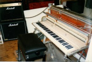
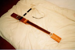
Is it a piano? Is it an electric guitar? Neither, it’s a hybrid! Keys, “action”, dampers from an upright piano, wood planks, electric guitar strings, and long pickup coils.
I first had the idea for the upright electric guitar in late 1986. At that time I had been scraping together a living for around 2 years, by hauling a 450-pound upright piano around to the shopping precincts in England, playing it as a street entertainer – and in my spare time I dreamt of having a keyboard instrument that would allow working with the sound of a “solid body” electric guitar. I especially liked the guitar sound of Angus Young from AC/DC, that of a Gibson SG. It had a lot of warmth in the tone, and whenever I heard any of their music, I kept thinking of all the things I might be able to do with that sound if it was available on a keyboard, such as developing new playing techniques. I had visions of taking rock music in new directions, touring, recording, and all the usual sorts of things an aspiring musician has on their mind.
Digital sampling was the latest development in keyboard technology back then, but I had found that samples of electric guitar did not sound authentic enough, even just in terms of their pure tone quality. Eventually all this led to one of those “eureka” moments in which it became clear that one way to get what I was after, would be to take a more “physical” approach by using a set of piano keys and the “action” and “dampering” mechanism that normally comes with them, and then, using planks of wood to mount on, swop out piano strings for those from an electric guitar, add guitar pickups, wiring and switches, and so on – and finally, to send the result of all this into a Marshall stack.
I spent much of the next 12 years working on some form of this idea, except for a brief interlude for a couple of years in the early 1990s, during which I collaborated with a firm based in Devon, Musicom Ltd, whose use of additive synthesis technology had led them to come up with the best artificially produced sounds of pipe organs that were available anywhere in the world. Musicom had also made some simple attempts to create other instrument sounds including acoustic piano, and the first time I heard one of these, in 1990, I was very impressed – it clearly had a great deal of the natural “warmth” of a real piano, warmth that was missing from any digital samples I had ever heard. After that first introduction to their technology and to the work that Musicom were doing, I put aside my idea for the physical version of the upright electric guitar for a time, and became involved with helping them with the initial analysis of electric guitar sounds.
Unfortunately, due to economic pressures, there came a point in 1992 when Musicom had to discontinue their research into other instrument sounds and focus fully on their existing lines of development and their market for the pipe organ sounds. It was at that stage that I resumed work on the upright electric guitar as a physical hybrid of an electric guitar and an upright piano.
I came to describe the overall phases of this project as “approaches”, and in this sense, all work done before I joined forces with Musicom was part of “Approach 1”, the research at Musicom was “Approach 2”, and the resumption of my original idea after that was “Approach 3”.
During the early work on Approach 1, my first design attempts at this new instrument included a tremolo or “whammy bar” to allow some form of note / chord bending. I made detailed 3-view drawings of the initial design, on large A2 sheets. These were quite complicated and looked like they might prove to be very expensive to make, and sure enough, when I showed them a light engineering firm, they reckoned it would cost around £5,000.00 for them to produce to those specifications. Aside from the cost, even on paper this design looked a bit impractical – it seemed like it might never stay in tune, for one thing.
Despite the apparent design drawbacks, I was able to buy in some parts during Approach 1, and have other work done, which would eventually be usable for Approach 3. These included getting the wood to be used for the planks, designing and having the engineering done on variations of “fret” pieces for all the notes the new instrument would need above the top “open E” string on an electric guitar, and buying a Marshall valve amp with a separate 4×12 speaker cabinet.
While collaborating with Musicom on the electronic additive synthesis method of Approach 2, I kept hold of most of the work and items from Approach 1, but by then I had already lost some of the original design drawings from that period. This is a shame, as some of them were done in multiple colours, and they were practically works of art in their own right. As it turned out, the lost drawings included features that I would eventually leave out of the design that resulted from a fresh evaluation taken to begin Approach 3, and so this loss did not stop the project moving forward.
The work on Approach 3 began in 1992, and it first involved sourcing the keys and action/dampering of an upright piano. I wanted to buy something new and “off the shelf”, and eventually I found a company based in London, Herrberger Brooks, who sold me one of their “Rippen R02/80” piano actions and key sets, still boxed up as it would be if sent to any company that manufactures upright pianos.
These piano keys and action came with a large A1 blueprint drawing that included their various measurements, and this turned out to be invaluable for the design work that had to be done next. The basic idea was to make everything to do with the planks of wood, its strings, pickups, tuning mechanism, frets, “nut”, machine heads and so on, fit together with, and “onto”, the existing dimensions of the piano keys and action – and to then use a frame to suspend the planks vertically, to add a strong but relatively thin “key bed” under the keys, legs under the key bed to go down to ground level and onto a “base”, and so on.
To begin work on designing how the planks would hold the strings, how those would be tuned, where the pickup coils would go and so on, I first reduced down this big blueprint, then added further measurements of my own, to the original ones. For the simplest design, the distance between each of the piano action’s felt “hammers” and the next adjacent hammer was best kept intact, and this determined how far apart the strings would have to be, how wide the planks needed to be, and how many strings would fit onto each plank. It looked like 3 planks would be required.
While working on new drawings of the planks, I also investigated what gauge of electric guitar string should be used for each note, how far down it would be possible to go for lower notes, and things related to this. With a large number of strings likely to be included, I decided it would be a good idea to aim for a similar tension in each one, so that the stresses on the planks and other parts of the instrument would, at least in theory, be relatively uniform. Some enquiries at the University of Bristol led me to a Dr F. Gibbs, who had already retired from the Department of Physics but was still interested in the behaviour and physics of musical instruments. He assisted with the equations for calculating the tension of a string, based on its length, diameter, and the pitch of the note produced on it. Plugging all the key factors into this equation resulted in a range of electric guitar string gauges that made sense for the upright electric guitar, and for the 6 open string notes found on a normal electric guitar, the gauges resulting from my calculations were similar to the ones your average electric guitarist might choose.
Other practicalities also determined how many more notes it would theoretically be possible to include below the bottom “open E” string on an electric guitar, for the new instrument. For the lowest note to be made available, by going all the way down to a 0.060 gauge wound string – the largest available at that time as an electric guitar string – it was possible to add several more notes below the usual open bottom E string. I considered using bass strings for notes below this, but decided not to include them and instead, to let this extra range be the lower limit on strings and notes to be used. Rather than a bass guitar tone, I wanted a consistent sort of electric guitar tone, even for these extra lower notes.
For the upper notes, everything above the open top E on a normal guitar would have a single fret at the relevant distance away from the “bridge” area for that string, and all those notes would use the same string gauge as each other.
The result of all the above was that the instrument would accommodate a total of 81 notes / strings, with an octave of extra notes below the usual guitar’s open bottom E string, and just under 2 octaves of extra notes above the last available fret from the top E string of a Gibson SG, that last fretted note on an SG being the “D” just under 2 octaves above the open top E note itself. For the technically minded reader, this range of notes went from “E0” to “C7”.
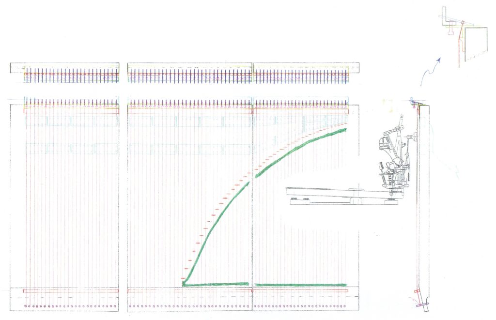
Having worked all this out, I made scale drawings of the 3 planks, with their strings, frets, pickup coils, and a simple fine-tuning mechanism included. It was then possible to manipulate a copy of the piano action blueprint drawing – with measurements removed, reduced in size, and reversed as needed – so it could be superimposed onto the planks’ scale drawings, to the correct relational size and so on. I did this without the aid of any computer software, partly because in those days, CAD apps were relatively expensive, and also because it was difficult to find any of this software that looked like I could learn to use it quickly. Since I had already drawn this to scale in the traditional way – using draftsman’s tools and a drawing board – it made sense to work with those drawings, so instead of CAD, I used photocopies done at a local printing shop, and reduced / reversed etc, as needed.
Key drawing of 3 planks, strings, frets, fine tuning mechanism and pickup coils, combined with upright piano action
It was only really at this point, once the image of the piano action’s schematic was married up to the scale drawings of the 3 planks, that I began to fully understand where this work was heading, in terms of design. But from then on, it was relatively easily to come up with the rest of the concepts and to draw something for them, so that work could proceed on the frame to hold up the planks, the key bed, legs, and a base at ground level.
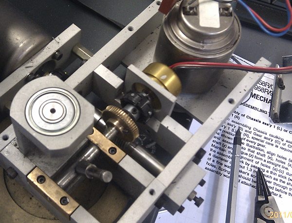
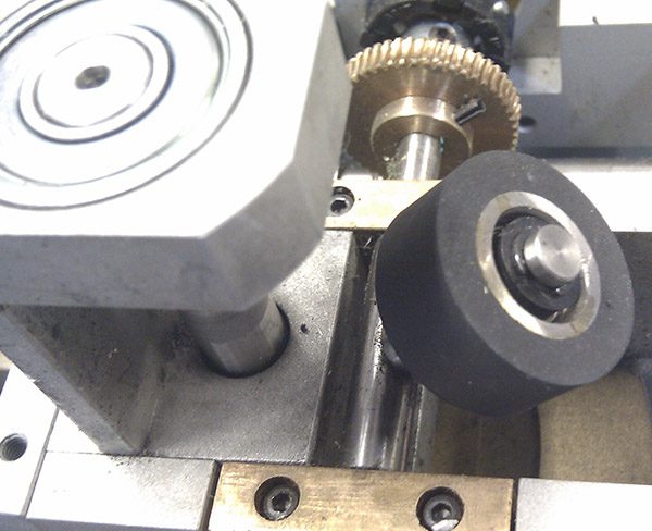
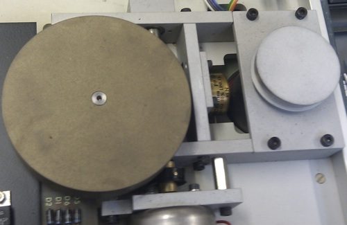
Around this time, I came across an old retired light engineer, Reg Huddy, who had a host of engineer’s machines – drill presses, a lathe, milling machine, and so on – set up in his home. He liked to make small steam engines and things of that nature, and when I first went to see him, we hit it off immediately. In the end he helped me make a lot of the metal parts that were needed for the instrument, and to machine in various holes and the pickup coil routing sections on the wood planks. He was very interested in the project, and as I was not very well off, he insisted in charging minimal fees for his work. Reg also had a better idea for the fine tuning mechanism than the one I had come up with, and we went with his version, as soon as he showed it to me.
If I am honest, I don’t think I would ever have finished the work on this project without all the help that Reg contributed. I would buy in raw materials if he didn’t already have them, and we turned out various parts as needed, based either on 3-view drawings I had previously come up with, or for other parts we realised would be required as the project progressed, from drawings I worked up as we went along. Reg sometimes taught me to use his engineering machinery, and although I was a bit hesitant at times, after a while I was working on these machines to a very basic standard.
I took the wood already bought for the instrument during the work on Approach 1, to Jonny Kinkead of Kinkade Guitars, and he did the cutting, gluing up and shaping to the required sizes and thicknesses for the 3 planks. The aim was to go with roughly the length of a Gibson SG neck and body, to make the planks the same thickness as an SG body, and to include an angled bit as usual at the end where an SG or any other guitar is tuned up, the “machine head” end. Jonny is an excellent craftsman and was able to do this work to a very high standard, based on measurements I provided him with.
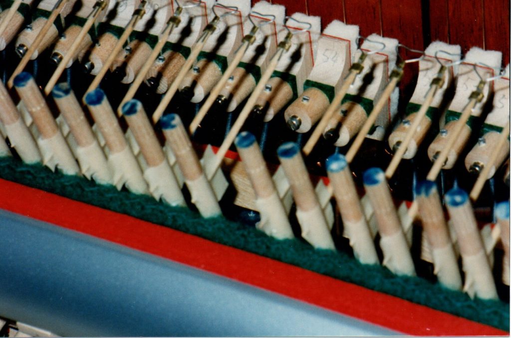
As well as getting everything made up for putting onto the planks, the piano action itself needed various modifications. The highest notes had string lengths that were so short that the existing dampers had to be extended so they were in the correct place, as otherwise they would not have been positioned over those strings at all. Extra fine adjustments were needed for each damper, so that instead of having to physically bend the metal rod holding a given damper in place – an inexact science at the best of times – it was possible to turn a “grub screw” to accomplish the same thing, but with a much greater degree of precision. And finally, especially important for the action, the usual felt piano “hammers” were to be replaced by smaller versions made of stiff wire shaped into a triangle. For these, I tried a few design mock-ups to find the best material for the wire itself, and to get an idea of what shape to use. Eventually, once this was worked out, I made up a “jig” around which it was possible to wrap the stiff wire so as to produce a uniformly shaped “striking triangle” for each note. This was then used to make 81 original hammers that were as similar to each other as possible. Although using the jig in this way was a really fiddly job, the results were better than I had expected, and they were good enough.
Close-up of a few hammers, dampers and strings
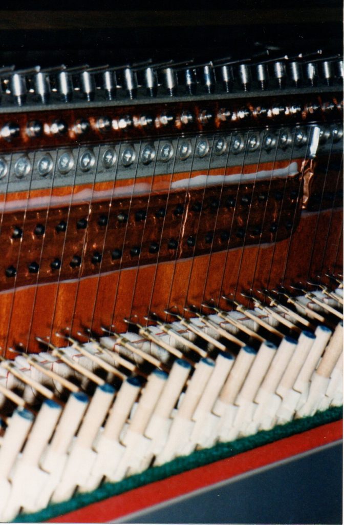
While this was all underway, I got in touch with an electric guitar pickup maker, Kent Armstrong of Rainbow Pickups. When the project first started, I had almost no knowledge of solid body electric guitar physics at all, and I certainly had no idea how pickup coils worked. Kent patiently explained this to me, and once he understood what I was doing, we worked out as practical a design for long humbucker coils as possible. A given coil was to go all the way across one of the 3 planks, “picking up” from around 27 strings in total – but for the rightmost plank, the upper strings were so short that there was not enough room to do this and still have both a “bridge” and a “neck” pickup, so the top octave of notes would had to have these two sets of coils stacked one on top of the other, using deeper routed areas in the wood than elsewhere.
For the signal to send to the amplifier, we aimed for the same overall pickup coil resistance (Ω) as on a normal electric guitar. By using larger gauge wire and less windings than normal, and by wiring up the long coils from each of the 3 planks in the right way, we got fairly close to this, for both an “overall bridge” and an “overall neck” pickup. Using a 3-way switch that was also similar to what’s found on a normal electric guitar, it was then possible to have either of these 2 “overall” pickups – bridge or neck – on by itself, or both at once. Having these two coil sets positioned a similar distance away from the “bridge end” of the strings as on a normal guitar, resulted in just the sort of sound difference between the bridge and neck pickups, as we intended. Because, as explained above, we had to stack bridge and neck coils on top of each other for the topmost octave of notes, those very high notes – much higher than on most electric guitars – did not sound all that different with the overall “pickup switch” position set to “bridge”, “neck”, or both at once. That was OK though, as those notes were not expected to get much use.
Some electric guitar pickups allow the player to adjust the volume of each string using a screw or “grub screw” etc. For the upright electric guitar I added 2 grub screws for every string and for each of the bridge and neck coils, and this means we had over 300 of these that had to be adjusted. Once the coils were ready, and after they were covered in copper sheeting to screen out any unwanted interference and they were then mounted up onto the planks, some early adjustments made to a few of these grub screws, and tests of the volumes of those notes, enabled working up a graph to calculate how much to adjust the height of each of the 300+ grub screws, for all 81 strings. This seemed to work quite well in the end, and there was a uniform change to volume from one end of the available notes to the other, one which was comparable to a typical electric guitar.
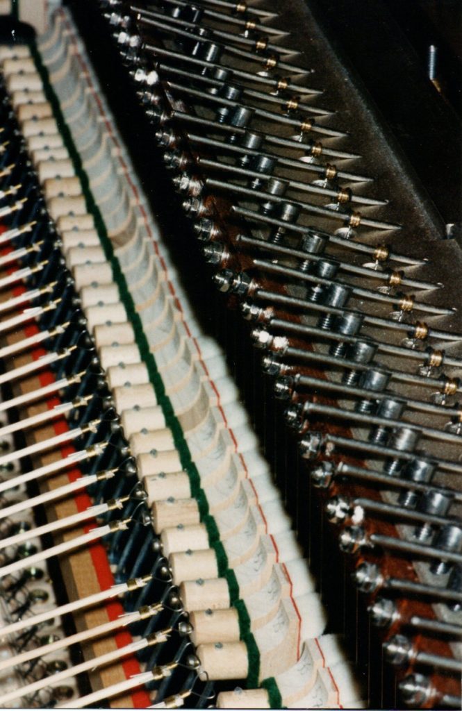
Unlike a normal electric guitar, fine tuning on this instrument was done at the “ball end” / “bridge end” of each string, not the “machine heads end” / “nut end”. The mechanism for this involved having a very strong, short piece of round rod put through the string’s “ball”, positioning one end of this rod into a fixed groove, and turning a screw using an allen key near the other end of the rod, to change the tension in the string. It did take a while to get this thing into tune, but I have always had a good ear, and over the years I had taught myself how to tune a normal piano, which is much more difficult than doing this fine tuning of the upright electric guitar instrument.
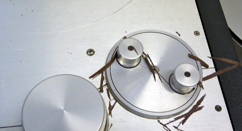
fine tuning mechanisms for each string (in the upper right part of the photo)
hammers, dampers, strings, pickup coils and their grub screws, and fine tuning mechanisms
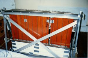
A frame made of aluminium was designed to support the 3 planks vertically. They were quite heavy on their own, and much more so with all the extra metal hardware added on, so the frame had to be really strong. Triangle shapes gave it extra rigidity. To offset the string tensions, truss rods were added on the back of the 3 planks, 4 per plank at equal intervals. When hung vertically, the 3 planks each had an “upper” end where the fine tuning mechanisms were found and near where the pickup coils were embedded and the strings were struck, and a “lower” end where the usual “nut” and “machine heads” would be found. I used short aluminium bars clamping each of 2 adjacent strings together in place of a nut, and zither pins in place of machine heads. The “upper” and “lower” ends of the planks were each fastened onto their own hefty piece of angle iron, which was then nestled into the triangular aluminium support frame. The result of this design was that the planks would not budge by even a tiny amount, once everything was put together. This was over-engineering on a grand scale, making it very heavy – but to my thinking at that time, this could not be helped.
The piano keys themselves also had to have good support underneath. As well as preventing sagging in the middle keys and any other potential key slippage, the “key bed” had to be a thin as possible, as I have long legs and have always struggled with having enough room for them under the keys of any normal piano. These 2 requirements – both thin and strong – led me to have some pieces of aluminium bar heat treated for extra strength. Lengths of this reinforced aluminium bar were then added “left to right”, just under the keys themselves, having already mounted the keys’ standard wooden supports – included in what came with the piano action – onto a thin sheet of aluminium that formed the basis of the key bed for the instrument. There was enough height between the keys and the bottom of these wooden supports, to allow a reasonable thickness of aluminium to be used for these left-to-right bars. For strength in the other direction of the key bed – “front to back” – 4 steel bars were added, positioned so that, as I sat at the piano keyboard, they were underneath but still out of the way. Legs made of square steel tubing were then added to the correct height to take this key bed down to a “base” platform, onto which everything was mounted. Although this key bed ended up being quite heavy in its own right, with the legs added it was as solid as a rock, so the over-engineering did at least work in that respect.
If you have ever looked inside an upright piano, you might have noticed that the “action” mechanism usually has 2 or 3 large round nuts you can unscrew, after which it is possible to lift the whole mechanism up and out of the piano and away from the keys themselves. On this instrument, I used the same general approach to do the final “marrying up” – of piano keys and action, to the 3 planks of wood suspended vertically. The existing action layout already had “forks” that are used for this, so everything on the 3 planks was designed to allow room for hefty sized bolts fastened down tightly in just the right spots, in relation to where the forks would go when the action was presented up to the planks. The bottom of a normal upright piano action fits into “cups” on the key bed, and I also used these in my design. Once the planks and the key bed were fastened down to the aluminium frame and to the base during assembly, then in much the same way as on an upright piano, the action was simply “dropped down” into the cups, then bolted through the forks and onto, in this case, the 3 planks.
It’s usually possible to do fine adjustments to the height of these cups on an upright piano, and it’s worth noting that even a tiny change to this will make any piano action behave differently. This is why it was so important to have both very precise tolerances in the design of the upright electric guitar’s overall structure, together with as much strength and rigidity as possible for the frame and other parts.
With a normal upright piano action, when you press a given key on the piano keyboard, it moves the damper for that single note away from the strings, and the damper returns when you let go of that key. In addition to this, a typical upright piano action includes a mechanism for using a “sustain pedal” with the right foot, so that when you press the pedal, the dampers are pushed away from all the strings at the same time, and when you release the pedal, the dampers are returned back onto all the strings. The upright piano action bought for this instrument did include all this, and I especially wanted to take advantage of the various dampering and sustain possibilities. Early study, drawing and calculations of forces, fulcrums and so on, eventually enabled use of a standard piano sustain foot pedal – bought off the shelf from that same firm, Herrberger Brooks – together with a hefty spring, some square hollow aluminium tube for the horizontal part of the “foot to dampers transfer” function, and a wooden dowel for the vertical part of the transfer. Adjustment had to be made to the position of the fulcrum, as the first attempt led to the foot pedal needing too much force, which made it hard to operate without my leg quickly getting tired. This was eventually fixed, and then it worked perfectly.
At ground level I designed a simple “base” of aluminium sheeting, with “positioners” fastened down in just the right places so that the legs of the key bed, the triangular frame holding up the 3 planks, and the legs of the piano stool to sit on, always ended up in the correct places in relation to each other. This base was also where the right foot sustain pedal and its accompanying mechanism were mounted up. To make it more transportable, the base was done in 3 sections that could fairly easily be fastened together and disassembled.
After building – further tests and possible modifications
When all this design was finished, all the parts were made and adjusted as needed, and it could finally be assembled and tried out, the first time I put the instrument together, added the wiring leads, plugged it into the Marshall stack, and then tuned it all up, it was a real thrill to finally be able to sit and play it. But even with plenty of distortion on the amp, it didn’t really sound right – it was immediately obvious that there was too much high frequency in the tone. It had wonderful amounts of sustain, but the price being paid for this was that the sound was some distance away from what I was really after. In short, the instrument worked, but instead of sounding like a Gibson SG – or any other electric guitar for that matter – it sounded a bit sh***y.
When I had first started working on this project, my “ear” for what kind of guitar sound I wanted, was in what I would describe as an “early stage of development”. Mock-up tests done during Approach 1, before 1990, had sounded kind of right at that time. But once I was able to sit and play the finished instrument, and to hear it as it was being played, with hindsight I realised that my “acceptable” evaluation of the original mock-up was more because, at that point, I had not yet learned to identify the specific tone qualities I was after. It was only later as the work neared completion, that my “ear” for the sound I wanted became more fully developed, as I began to better understand how a solid body electric guitar behaves, what contributes to the tone qualities you hear from a specific instrument, and so on.
I began asking some of the other people who had been involved in the project, for their views on why it didn’t sound right. Two things quickly emerged from this – it was too heavy, and the strings were being struck, instead of plucking them.
Kent Armstrong, who made the pickups for the upright electric guitar, told me a story about how he once did a simple experiment which, in relation to my instrument, demonstrated what happens if you take the “it’s too heavy” issue to the extreme. He told me about how he had once “made an electric guitar out of a brick wall”, by fastening an electric guitar string to the wall at both ends of the string, adding a pickup coil underneath, tuning the string up, sending the result into an amp, and then plucking the string. He said that this seemed to have “infinite sustain” – the sound just went on and on. His explanation for this was that because the brick wall had so much mass, it could not absorb any of the vibration from the string, and so all of its harmonics just stayed in the string itself.
Although this was a funny and quite ludicrous example, I like this kind of thing, and the lesson was not lost on me at the time. We discussed the principles further, and Kent told me that in his opinion, a solid body electric guitar needs somewhere around 10 to 13 pounds of wood mass, in order for it to properly absorb the strings’ high harmonics in the way that gives you that recognisable tone quality we would then call “an electric guitar sound”. In essence, he was saying that the high frequencies have to “come out”, and then it’s the “warmer” lower harmonics which remain in the strings, that makes an electric guitar sound the way it does. This perfectly fit with my own experience of the tones I liked so much, in a guitar sound I would describe as “desirable”. Also, it did seem to explain why my instrument, which had a lot more “body mass” than 10 to 13 pounds – with its much larger wood planks, a great deal of extra hardware mounted onto them, and so on – did not sound like that.
As for striking rather than plucking the strings, I felt that more trials and study would be needed on this. I had opted to use hammers to strike the strings, partly as this is much simpler to design for – the modifications needed to the upright piano action bought off the shelf, were much less complicated than those that would have been required for plucking them. But there was now a concern that the physics of plucking and striking might be a lot different to each other, and if so there might be no way of getting around this, except to pluck them.
I decided that in order to work out what sorts of changes would best be made to the design of this instrument to make it sound better, among other things to do as a next step, I needed first-hand experience of the differences in tone quality between various sizes of guitar body. In short, I decided to make it my business to learn as much as I could about the physics of the solid body electric guitar, and if necessary, to learn more than perhaps anyone else out there might already know. I also prepared for the possibility that a mechanism to pluck the strings might be needed.
At that time, in the mid 1990s, there had been some excellent research carried out on the behaviour of acoustic guitars, most notably by a Dr Stephen Richardson at the University of Cardiff. I got in touch with him, and he kindly sent me details on some of this work. But he admitted that the physics of the acoustic guitar – where a resonating chamber of air inside the instrument plays a key part in the kinds of sounds and tones that the instrument can make – is fundamentally different to that of a solid body electric guitar.
I trawled about some more, but no one seemed to have really studied solid body guitar physics – or if they had, nothing had been published on it. Kent Armstrong’s father Dan appeared on the scene at one point, as I was looking into all this. Dan Armstrong was the inventor of the Perspex bass guitar in the 1960s. When he, Kent and I all sat down together to have a chat about my project, it seemed to me that Dan might in fact know more than anyone else in the world, about what is going on when the strings vibrate on a solid body guitar. It was very useful to hear what he had to say on this.
I came away from all these searches for more knowledge, with further determination to improve the sound of the upright electric guitar. I kept an eye out for a cheap Gibson SG, and as luck would have it, one appeared online for just £400.00 – for any guitar enthusiasts out there, you will know that even in the 1990s, that was dirt cheap. I suspected there might be something wrong with it, but decided to take a risk and buy it anyway. It turned out to have a relatively correct SG sound, and was cheap because it had been made in the mid 1970s, at a time when Gibson were using inferior quality wood for the bodies of this model. While it clearly did not sound as good as, say, a vintage SG, it was indeed a Gibson original rather than an SG copy, and it did have a “workable” SG sound that I could compare against.
I also had a friend with a great old Gibson SG Firebrand, one that sounded wonderful. He offered to let me borrow it for making comparative sound recordings and doing other tests. I was grateful for this, and I did eventually take him up on the offer.
One thing that I was keen to do at this stage, was to look at various ways to measure – and quantify – the differences in tone quality between either of these two Gibson SGs and the upright electric guitar. I was advised to go to the Department of Mechanical Engineering at the University of Bristol, who were very helpful. Over the Easter break of 1997, they arranged for me to bring in my friend’s SG Firebrand and one of my 3 planks – with its strings all attached and working – so that one of their professors, Brian Day, could conduct “frequency sweep” tests on them. Brian had been suffering from early onset of Parkinson’s disease and so had curtailed his normal university activities, but once he heard about this project, he was very keen to get involved. Frequency sweep tests are done by exposing the “subject” instrument to an artificially created sound whose frequency is gradually increased, while measuring the effect this has on the instrument’s behaviour. Brian and his colleagues carried out the tests while a friend and I assisted. Although the results did not quite have the sorts of quantifiable measurements I was looking for, they did begin to point me in the right direction.
After this testing, someone else recommended I get in touch with a Peter Dobbins, who at that time worked at British Aerospace in Bristol and had access to spectral analysis equipment at their labs, which he had sometimes used to study the physics of the hurdy gurdy, his own personal favourite musical instrument. Peter was also very helpful, and eventually he ran spectral analysis of cassette recordings made of plucking, with a plectrum, the SG Firebrand, the completed but “toppy-sounding” upright electric guitar, and a new mock-up I had just made at that point, one that was the same length as the 3 planks, but only around 4 inches wide. This new mock-up was an attempt to see whether using around 12 or 13 much narrower planks in place of the 3 wider ones, might give a sound that was closer to what I was after.
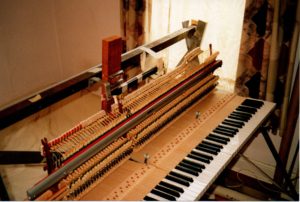
Mock-up of possible alternative to 3 planks – would 12 or 13 of these sound better instead? Shown on its own (with a long test coil), and mounted up to the keys and action setup so that plucking tests could make use of the dampers to stop strings moving between recordings of single notes
As it turned out, the new mock-up did not sound that much different to the completed upright electric guitar itself, when the same note was plucked on each of them. It was looking like there was indeed a “range” of solid guitar body mass / weight of wood that gave the right kind of tone, and that even though the exact reasons for the behaviour of “too much” or “too little” mass might be different to each other, any amount of wood mass / weight on either side of that range, just couldn’t absorb enough of the high harmonics out of the strings. Despite the disappointing result of the new mock-up sounding fairly similar to the completed instrument, I went ahead and gave Peter the cassette recordings of it, of the completed instrument, and of my friend’s SG Firebrand, and he stayed late one evening at work and ran the spectral analysis tests on all of these.
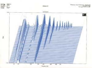
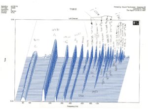
Peter’s spectral results were just the kind of thing I had been after. He produced 3D graphs that clearly showed the various harmonics being excited when a given string was plucked, how loud each one was, and how long they went on for. This was a pictorial, quantitative representation of the difference in tone quality between my friend’s borrowed SG Firebrand, and both the completed instrument and the new mock-up. The graphs gave proper “shape” and “measure” to these differences. By this time, my “ear” for the sort of tone quality I was looking for, was so highly developed that I could distinguish between these recordings immediately, when hearing any of them. And what I could hear, was reflected precisely on these 3D graphs.
Spectral analysis graphs in 3D, of Gibson SG Firebrand “open bottom E” note plucked, and the same note plucked on the upright electric guitar. Frequency in Hz is on the x axis and time on the y axis, with time starting at the “back” and moving to the “front” on the y axis. Harmonics are left-to-right on each graph – leftmost is the “fundamental”, then 1st harmonic etc. Note how many more higher harmonics are found on the right graph of the upright electric guitar, and how they persist for a long time. I pencilled in frequencies for these various harmonics on the graph on the right, while studying it to understand what was taking place on the string.
While this was all underway, I also mocked up a few different alternative types of hammers and carried out further sound tests to see what sort of a difference you would get in tone, from using different materials for these, but always still striking the string. Even though I was more or less decided on moving to a plucking mechanism, for completeness and full understanding, I wanted to see if any significant changes might show up from using different sorts of hammers. For these experiments, I tried some very lightweight versions in plastic, the usual felt upright piano hammers, and a couple of others that were much heavier, in wood. Not only was there almost no difference whatsoever between the tone quality that each of these widely varied types of hammers seemed to produce, it also made next to no difference where, along the string, you actually struck it.
Other hammer designs tried – there was little variation in the sound each of these produced
These experiments, and some further discussions with a guitar maker who had helped out on the project, brought more clarification to my understanding of hammers vs plucking. Plucking a string seems to make its lower harmonics get moving right away, and they then start out with more volume compared to that of the higher harmonics. The plucking motion will always do this, partly because there is so much energy being transferred by the plectrum or the player’s finger – and this naturally tends to drive the lower harmonics more effectively. When you hit a string with any sort of hammer though, the effect is more like creating a sharp “shock wave” on the string, but one with much less energy. This sets off the higher harmonics more, and the lower ones just don’t get going properly.
In a nutshell, all of this testing and research confirmed the limitations of hammers, and the fact that there are indeed fundamental differences between striking and plucking an electric guitar string. Hammers were definitely “out”.
To summarise the sound characteristic of the upright electric guitar, its heavy structure and thereby the inability of its wood planks to absorb enough high frequencies out of the strings, made it naturally produce a tone with too many high harmonics and not enough low ones – and hitting its strings with a hammer instead of plucking, had the effect of “reinforcing” this tonal behaviour even more, and in the same direction.
The end?
By this point in the work on the project, as 1998 arrived and we got into spring and summer of that year, I had gotten into some financial difficulties, partly because this inventing business is expensive. Despite having built a working version of the upright electric guitar, even aside from the fact that the instrument was very heavy and took some time to assemble and take apart – making it impractical for taking on tour for example – the unacceptable sound quality alone, meant that it was not usable. Mocked-up attempts to modify the design so that there would be many planks, each quite narrow, had not improved the potential of the sound to any appreciable degree, either.
I realised that I was probably reaching the end of what I could achieve on this project, off my own back financially. To fully confirm some of the test results, and my understanding of what it is that makes a solid body electric guitar sound the way it does, I decided to perform a fairly brutal final test. To this end, I first made recordings of plucking the 6 open strings on the cheap SG I had bought online for £400.00. Then I had the “wings” of this poor instrument neatly sawn off, leaving the same 4-inch width of its body remaining, as the new mock-up had. This remaining width of 4 inches was enough that the neck was unaffected by the surgery, which reduced the overall mass of wood left on the guitar, and its shape, down to something quite similar to that of the new mock-up.
I did not really want to carry out this horrible act, but I knew that it would fully confirm all the indications regarding the principles, behaviours and sounds I had observed in both the 3 planks of the completed upright electric guitar, in the new mock-up, and in other, “proper” SG guitars that, to my ear, sounded right. If, by doing nothing else except taking these lumps of wood mass away from the sides of the cheap SG, its sound went from “fairly good” to “unacceptably toppy”, it could only be due to that change in wood mass.
After carrying out this crime against guitars by chopping the “wings” off, I repeated the recordings of plucking the 6 open strings. Comparison to the “before” recordings of it, confirmed my suspicions – exactly as I had feared and expected, the “after” sound had many more high frequencies in it. In effect I had “killed” the warmth of the instrument, just by taking off those wings.
In September 1998, with no more money to spend on this invention, and now clear that the completed instrument was a kind of “design dead end”, I made the difficult decision to pull the plug on the project. I took everything apart, recycled as many of the metal parts as I could (Reg Huddy was happy to have many of these), gave the wood planks to Jonny Kinkead for him to use to make a “proper” electric guitar with as he saw fit, and then went through reams of handwritten notes, sketches and drawings from 12 years of work, keeping some key notes and drawings which I still have today, but having a big bonfire one evening at my neighbour’s place, with all the rest.
Some “video 8” film of the instrument remained, and I recently decided to finally go through all of that, and all the notes and drawings kept, and make up a YouTube video from it. This is what Greatbear Analogue & Digital Media has assisted with. I am very pleased with the results, and am grateful to them. Here is a link to that video: https://youtu.be/pXIzCWyw8d4
As for the future of the upright electric guitar, in the 20 years since ceasing work on the project, I have had a couple of ideas for how it could be redesigned to sound better and, for some of those ideas, to also be more practical.
One of these new designs involves using similar narrow 4-inch planks as on the final mockup described above, but adding the missing wood mass back onto this as “wings” sticking out the back – where they would not be in the way of string plucking etc – positioning the wings at a 90-degree angle to the usual plane of the body. This would probably be big and heavy, but it would be likely to sound a lot closer to what I have always been after.
Another design avenue might be to use 3 or 4 normal SGs and add robotic plucking and fretting mechanisms, driven by electronic sensors hooked up to another typical upright piano action and set of keys, with some programmed software to make the fast decisions needed to work out which string and fret to use on which SG guitar for each note played on the keyboard, and so on. While this would not give the same level of intimacy between the player and the instrument itself as even the original upright electric guitar had, the tone of the instrument would definitely sound more or less right, allowing for loss of “player feeling” from how humans usually pluck the strings, hold down the frets, and so on. This approach would most likely be really expensive, as quite a lot of robotics would probably be needed.
An even more distant possibility in relation to the original upright electric guitar, might be to explore additive synthesis further, the technology that the firm Musicom Ltd – with whom I collaborated during Approach 2 in the early 1990s – continue to use even today, for their pipe organ sounds. I have a few ideas on how to go about such additive synthesis exploration, but will leave them out of this text here.
As for my own involvement, I would like nothing better than to work on this project again, in some form. But these days, there are the usual bills to pay, so unless there is a wealthy patron or perhaps a sponsoring firm out there who can afford to both pay me enough salary to keep my current financial commitments, and to also bankroll the research and development that would need to be undertaken to get this invention moving again, the current situation is that it’s very unlikely I can do it myself.
Although that seems a bit of a shame, I am at least completely satisfied that, in my younger days, I had a proper go at this. It was an unforgettable experience, to say the least!
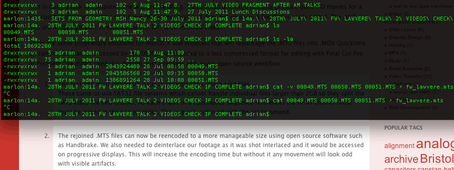
Digitising legacy and obsolete video formats in essence is simple but the technical details make the process more complex. Experience and knowledge are therefore needed to make the most appropriate choices for the medium.
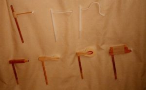
The U-matic video format usually had two types of video output, composite and a y/c type connector that Sony named ‘Dub’. Originally designed as a higher quality method to make analogue ‘dubs’, or for connections in an edit suite, the Dub connector offers a higher performance signal path for the video signal.
It would make sense to use the higher quality dub output when digitising U-matic tapes but here lies the problem. Firstly the connector uses the larger 7 pin y/c type connector that can be quite hard to find connectors for.
Secondly and most significantly, the chrominance subcarrier frequency is not the standard PAL 4.43Mhz but down converted by U-matic recorders to 0.686Mhz for low band recordings and 0.984Mhz for high band recordings.
What this means in practice is that you’ll only get a monochrome image using the U-matic dub connector unless you can find a way to convert the chroma subcarrier frequency back to 4.43Mhz.
There are several solutions:
Convert this Dub signal chroma frequency using one of a few older Timebase Correctors / Frame Synchronisers from the U-matic era.
These are now rare and often have other other faults that would degrade the signal.
Take the Luma and Chroma signals at the correct frequency directly from certain test points on the circuit boards inside the machines.
This can work well but is a slightly ‘messy’ solution and makes it hard to swap machines around, which is a necessity with older hardware.
Convert the dub signal using a dedicated external dub – y/c converter circuit. This is our preferred solution that works well technically. It is flexible enough to swap around to different machines easily. It is also a relatively simple circuit that is easy to repair and doesn’t subject the video signal to unnecessary extra processing.
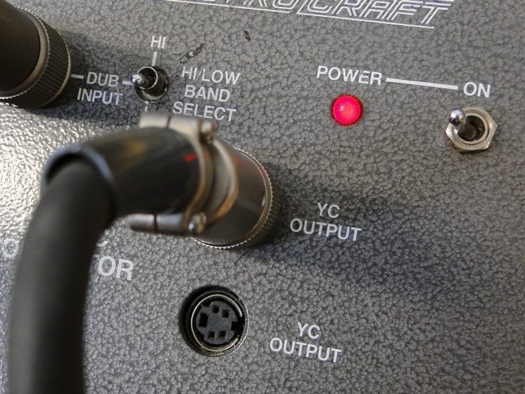
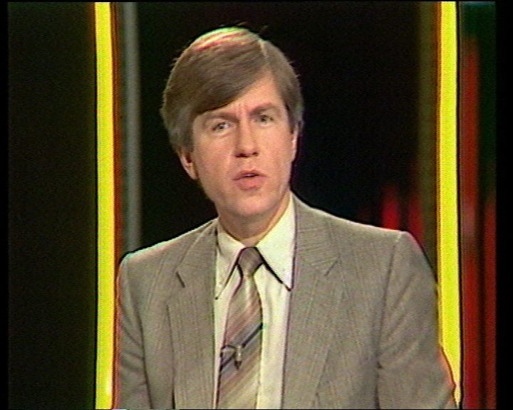
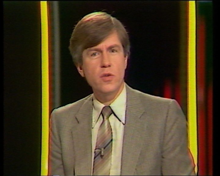
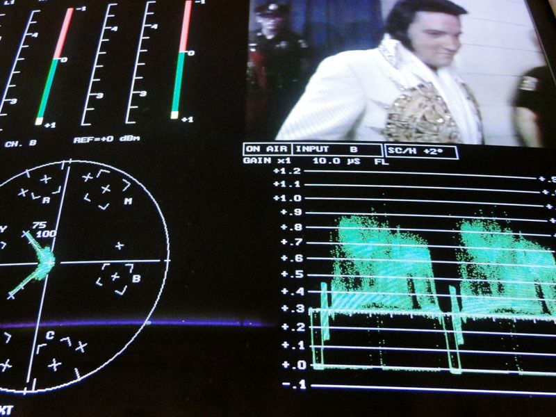
Below are two stills taken from a Apple ProRes recording from a Low Band PAL U-matic tape.
The first image is via the Dub connecter but converted to PAL Y/C.
The second images is via the Composite video out.
It’s clear from the images that there is more fine detail in the picture from the U-matic Dub version. The pattern / texture in the jacket and the texture and tone in the face is more detailed. In contrast, the version digitised through the Composite video connector has less noise but due to the extra encoding and decoding there is less detail and more ‘blurring’.
While less noise may be preferable in some instances, having the option to choose between these two is always better. It’s this kind of attention detail and investment in equipment and knowledge that we are proud of and makes us a preferred supplier of digitising services for U-matic video tape.
8 track cartridges were a very popular domestic audio format in the United States, although there were also sold in the UK and Europe. The growth of the 8 track was synonymous with its use in car industry, as it allowed people to listen to music on the move.
Although phased out in the early 1980s as CDs became increasingly popular, the 8 track retains a cult following, as demonstrated by this video which takes a virtual tour around the 8 track museum in Dallas, Texas, USA.
For a while now we’ve been working with film maker Jeanie Finlay on various projects, digitising archive video footage in varying tape formats and standards.
Her latest project, soon to be premiered in the US:
…is a film about truth, lies and the legacy of faking everything in the desperate pursuit of fame. The American dream, told by people who’d never even been to America.
We digitised a collection of VHS and Hi8 camcorder and full sized tapes and delivered Apple ProRes files for the edit.
See the trailer here:
From U-matic to VHS, Betacam to Blu Ray, Standard Definition to High Definition, the formats we use to watch visual media are constantly evolving.
Yet have you ever paused to consider what is at stake in the changing way audio-visual media is presented to us? Is viewing High Definition film and television always a better experience than previous formats? What is lost when the old form is supplanted by the new?
At Greatbear we have the pleasure of seeing the different textures, tones and aesthetics of tape-based Standard Definition video on a daily basis. The fuzzy grain of these videos contrasts starkly with the crisp, heightened colours of High Definition digital media we are increasingly used to seeing now on television, smartphones and tablets.
At Greatbear we always have one foot in the past, and one foot in the future. We act as a conduit between old and new media, ensuring that data stored on older media can continue to have a life in today’s digital intensive environments.
In 2012 Greatbear digitised a selection of audio and audio-visual tape for the Heritage Lottery Funded exhibition, Music & Liberation.
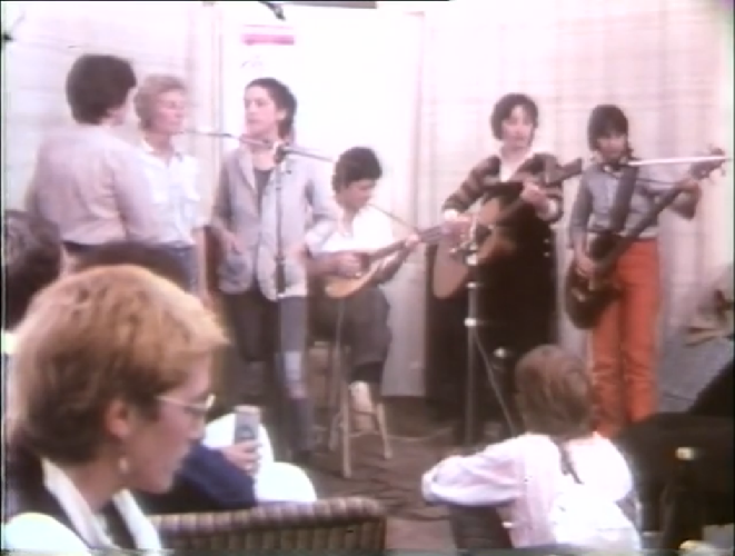
The first job was to migrate a short film by a feminist film making collective called Women in Moving Pictures who were based in Bristol in the early 1980s. The film shows how the Bristol Women’s Music Collective were using feminism to politicise music making and includes footage music workshops, group performances interspersed with self-defence classes and intimate conversations.
Film still from ‘In Our Own Time’
Several copies of the film had been stored in the Feminist Archive South, including the master copies. Out of curiosity the U-matic copy was initially digitised, before the original was migrated to high definition digital format.
Film Still from ‘In Our Own Time’
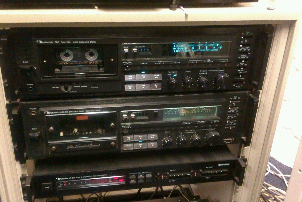
Another job digitsed a series of rare recordings on tape, donated by Maggie Nicols. This included rare footage of the pioneering Feminist Improvising Group, whose members included Sally Potter, Georgina Born and Lindsay Cooper. One of the tapes was originally recorded at half speed, a technique used to get more recording time. We used the Nakamichi 680 Discrete Head Cassette Deck to play back the tapes at the correct speed to ensure the highest quality transfer.
We also digitised a series of tapes from the open improvisation collective Maggie co-founded in 1980, Contradictions. This included the performance ‘Madness in a Circle’ and many other creative experiments.
Music & Liberation re-opens at Space Station Sixty-Five in London for the last four days of its UK-wide tour on 10 January, so if you want to listen to the music or watch the films make sure you catch it.
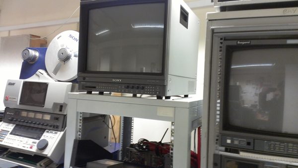
With the work we are involved with we have to use, keep working and store a large amount of old and usually large tape machines and other electronics. With a couple of machines it’s easy to store and easy to connect but as you grow and the variety and scope of machines develops it can soon become a wiring and space nightmare.
Racks and patchbays are the answer and the time’s come to rewire our racks as many new / old machines have joined our collection as has different types of digitising work. Key to this is the need to accurately monitor and digitise several sources while having the flexibility to change the workflow quickly whenever.
Richard from westent is providing support in this video redesign and it will be an interesting challenge mixing the old with the new to get the highest quality transfers with the most efficiency.
Greatbear protects tape-based analogue and digital media from the wave of obsolescence faced by these formats. The speed of technological change in the 20th and 21st centuries has been, and continues to be, breathtaking. Consider the amount of tapes and machines that have been made since the invention of magnetic recording tape by Valdemar Poulson in 1894. Since then, the drive for efficiency and better quality has fueled the development of numerous formats which become eclipsed as each new product hits the market.
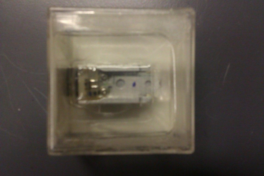
Close up of an individual V-MAG Head off an AMPEX 1″ Machine
Obsolescence for video tape is an issue for a number of reasons. Firstly the knowledge of how to repair older video machines is disappearing: as technology changes, people are no longer trained in the maintenance of such technology.
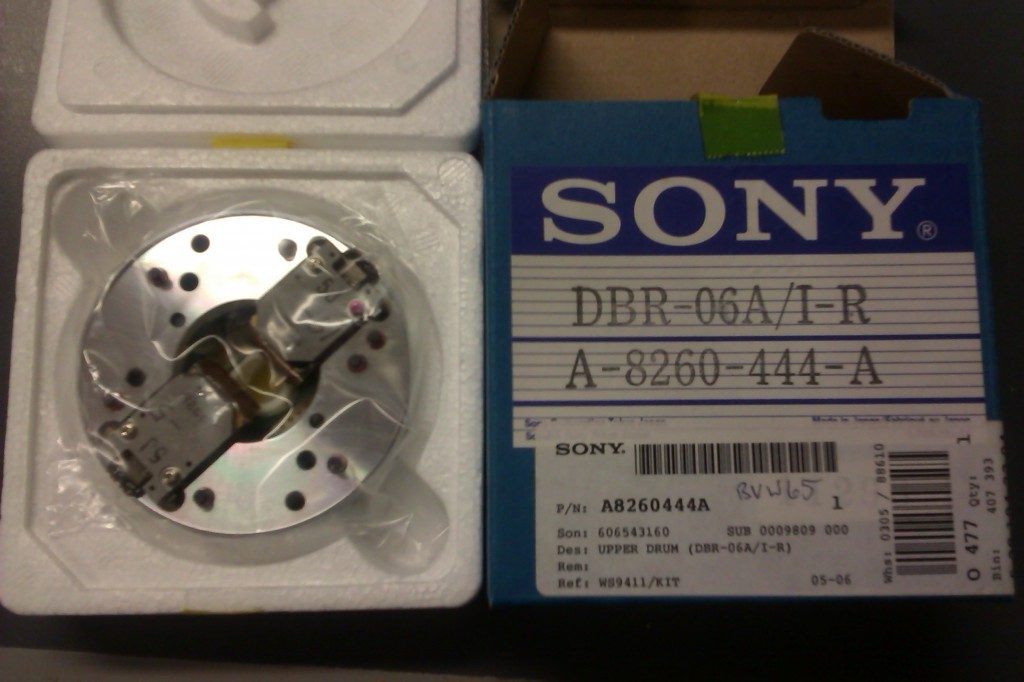
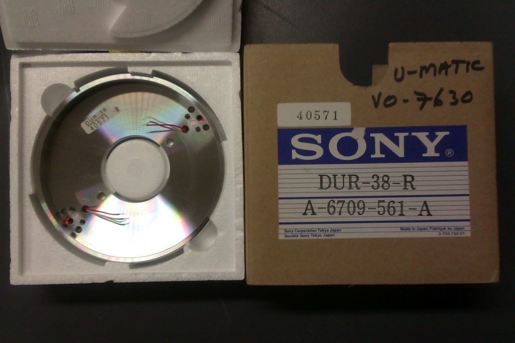
Another crucial issue is the lack of spare parts. For video tape machines, the most sought after parts are often drum heads. Video drum heads are difficult and expensive to make, they can’t be refurbished and there is no commercial market for them, which makes them rare and sought after.
The nature of recording an audio signal is different from recording a video signal. Because of this, video heads and the video tape transport had to be designed in a different way to audio heads. Audio drum heads are in fact easier to make and they can also be ‘relapped‘ (a sophisticated form of sanding down), so it is a fairly straightforward process to refurbish them.
Because of the specific problems facing video tape obsolescence we have to rely on ‘New Old Stock’, although sometimes it is possible to use parts from scrap machines. These are however less reliable because the drums heads are part of a mechanical process and if used extensively, they will inevitably be worn down.
Betacam Head Drum
One company – Video Magnetics Inc – remake video drum heads and specialise in the repair and alignment of Betacam SP, Digital Betacam, Betacam SX, DVCAM and DVC PRO recorders, cameras, camcorders and dockables.They do not however cover all the machines we use at Greatbear.
Luckily we are well stocked up with lots of spare parts, mainly through careful collecting with an eye to work in the future.
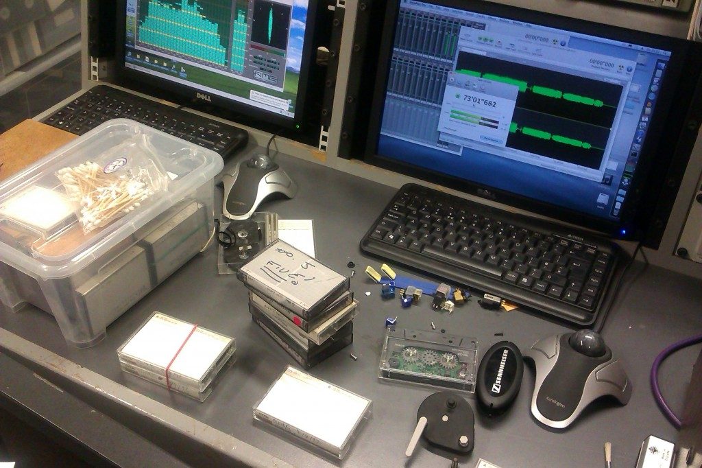
A selection of images from the Greatbear engine room on a typical day at the office.
Repairing, cleaning, baking, testing, sorting and transferring are our daily bread. The work is done to the backdrop of miscellaneous audio and audio-visual recordings ranging from early 1990s house music to ethnomusicological field recordings, corporate archives and everything else in-between.
As well as analogue tape, at Greatbear we also migrate digital tape to digital files. Digital media has become synonymous with the everyday consumption of information in the 21st century. Yet it may come as a surprise for people to encounter digital tape when we are so comfortable with the seemingly formless circulation of digital information on computers, at the cinema, on televisions, smartphones, tablets and other forms of mobile media. It is important to remember that digital information has a long history, and it doesn’t need to be binary or electronic – abacuses, Morse code and Braille are all examples of digital systems.
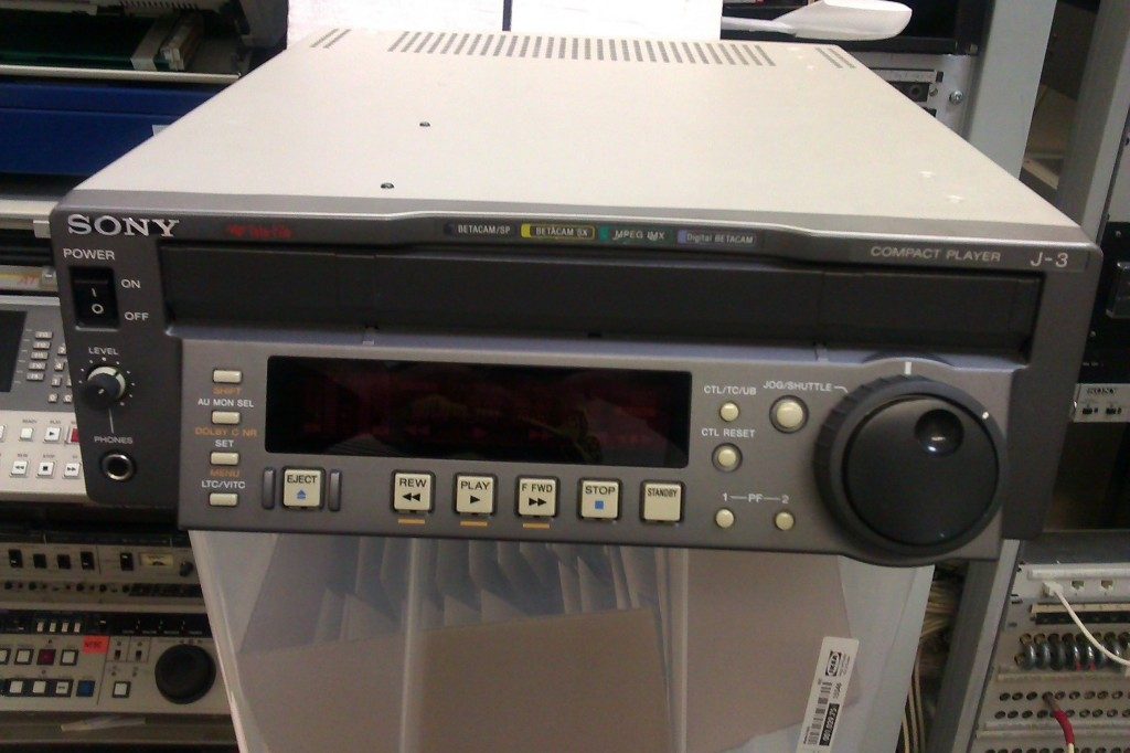
Digital Betacam tapes were launched in 1993 and superseded both Betacam and Betacam SP. Betacam remains the main acquisition and delivery format for broadcasting because there is very little compression on the tape. It is a very reliable format because it has a tried and tested mature transport mechanism.
While Digital Betacam is a current broadcast format, technology will inevitably move on – there is often a 10 year lifespan for broadcast media, as the parent company (SONY in this case) will cease to support the playing machines through selling spare parts.
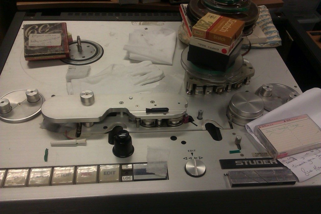
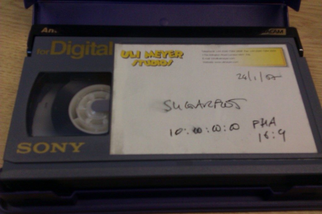
We were sent some Digital Betacam tapes by Uli Meyer Animation Studios who are based in London. Uli Meyer make 3 and 2 D commercials, long and short films and TV commercials. 5-10 years ago the company would have had Digital Betacam machines, but as technology develops it becomes harder to justify keeping machines that can take up a lot of physical space.
Workflow in broadcasting is also becoming increasingly ‘tape less’, making digital tape formats surplus to requirements. Another issue facing the Digital Betacam is that it records information in Standard Definition format. With broadcasters using High Definition only, the need to transfer digital information in line with contemporary technological requirements is imperative for large parts of industry.
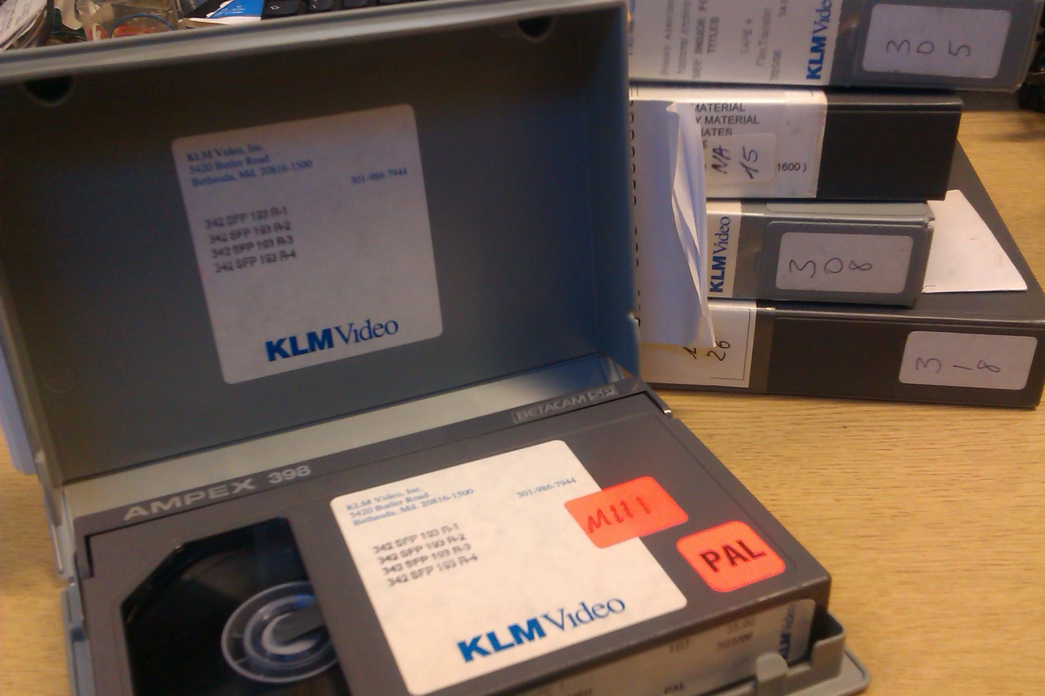
We have recently been digitising Betacam SP (‘superior performance’) video recordings, a cassette based component analogue format that is used extensively in the broadcast world. Betacam SP offered fantastic video and audio quality from its introduction in 1986, and a very similar digital cassette, Digital Betacam, is still used now.
Betacam SP was commonly used throughout the ’90s and ’00s and was not threatened with obsolescence as many older formats are. However Betacam VTR machines will soon become very hard to find spares for, thus becoming another threatened video tape format. Luckily at Greatbear we have every type of Betacam machine (PAL and NTSC) available, as well as spare parts (such as head drums), so we are able to migrate analogue formats to digital so they can be utilised by current media practitioners.
The tapes that have inspired this post are public domain tapes from the National Archives in the USA. They feature the tension filled politics of the Cold War, including footage of President John F. Kennedy, missile silos, Stalin, B29s taking off, graphics of the Iron Curtain, air raid warnings and people running into shelters. Collectively they give a powerful impression of Cold War international relations from the perspective of the American government.
The tapes were sent to us by renowned investigative journalist Paul Lashmar and were the raw material for his BBC Timewatch programme Baiting the Bear: How the real life Doctor Strangelove brought us close to Armageddon, aired in 1996.
Paul has covered many of the main news stories of the past 30 years related to terrorism, intelligence, organised crime, offshore crime, business fraud and the Cold War. He has written for newspapers such as the Independent on Sunday, the Guardian and the Evening Standard, is a regular TV and radio broadcaster and a lecturer in journalism at Brunel University.
We were recently contacted by Frank Whelan of the Comhaltas Regional Resource Centre who wanted us to digitise a recording of the Fleadh Cheoil traditional music festival in Buncranna, Co. Donegal in 1975.
Frank sent us an EIAJ ½ inch video that was recorded on a Sony High Density V-60H video tape for Helican Scan Video Tape Recorder. The tape was suffering from binder hydrolysis (often referred to as sticky shed syndrome), so needed treatment before it could be played. The tape was incubated and cleaned before the digitisation process.
The recording contains fascinating footage of solo and group performers from the biggest traditional Irish musical festival in the world. The first Fleadh Cheoil took place in 1951 and has happened every year since. Comhaltas are currently collecting archive material for every year the festival was held in order to create a document for future generations. The digitised film will go towards an exhibition and will be stored in a research facility focused on Irish traditional music.
This is an excerpt of the film that Frank kindly said we could use on our site.
At Greatbear we work on a range of digitising projects from national collections to personal one-offs. Today we received a ¼ inch open reel polyester and acetate based tape from Carmarthen based teacher Richard Lewis. The tapes are a good example of the types of personal material we are entrusted to digitise. The tapes are rare and valuable recordings of a choir performance in Hereford Cathedral in the mid-1960s.
Richard sang in Hereford Cathedral Choir from when he was 10-14 as a soprano and his father, Albert Lewis, played the church organ. Richard thinks there may be recordings of his Great Aunt on the tape, but isn’t sure because he hasn’t been able to listen to it for years. He says ‘he is fascinated to know to what is on the tape’ and is looking forward to hearing the digitised results.
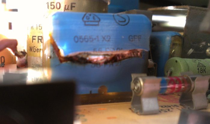
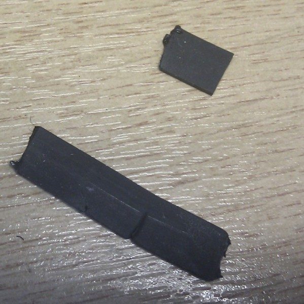
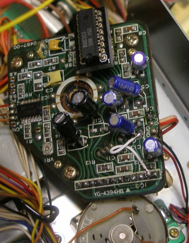
Yet again bad capacitors have reared their electrolytic fluid! This time in a Grundig Video 2000 video tape player, or V2000.
Pictured above is a X2 mains film cap in the power supply of the video machine, made by Frako. This brand of capacitors are German and used in many Studer audio tape machines too which commonly have similar smoking fun such as the B67 and sometimes the A80.
A nice satisfying repair though – all Frako film and electrolytic capacitors were desoldered and replaced with 105 degrees rated Panasonics. The circuit boards on these type of machines are also well made with thick tracks so there’s little risk of lifting solder pads with this type of repair.
Other than their ageing capacitors and some dry solder joint problems these Grundig machines are excellent although as with many older domestic formats the important proprietory spares like the V2000 upper head drums are very rare new now so keeping these machines running will get harder and more expensive over time.
This format was commonly used in education and in industry and was much cheaper than the U-matic and one inch formats.
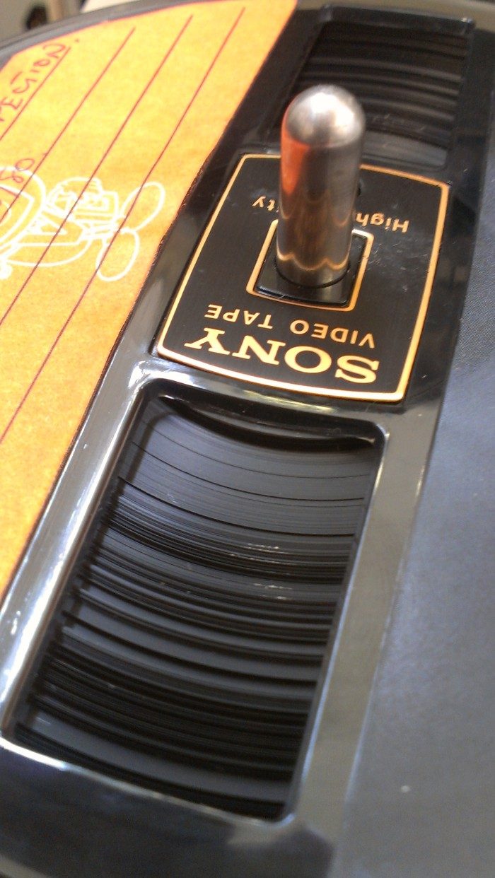
We usually see Scotch and Sony branded tape stock in this format. The Sony tape, is absolutely unplayable and dangerously so. It becomes ‘sticky’ or suffers from binder hydrolysis as Ampex audio tape commonly does. The tape will squeal loudly on any fixed guides and often stop moving around the head drum often damaging the head tips.
This tape can be restored and recovered but must be dehydrated at a very stable and constant low temperature. We’ve found this tape takes much longer than audio tape in this process and it’s also necessary to address any tape pack slip too. Custom winding machines are essential here as winding this tape on the vintage machines necessary for playback is too aggressive.
The image to the right is a tape we received and has an uneven tape pack and a small amount of mould growth too.
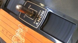
After dehydrating, winding and cleaning the tape and and tape pack looks more like this:
Early tape based digital formats such as DAT, Tascam DTRS and ADAT, etc are often problematic now, partly with tape issues and also reliability and spares availability. In 20 or even 10 years time these machines will be much less serviceable than the analogue tape machines of the previous generation and as a result more obsolete and a higher priority to migrate to a file based digital format.
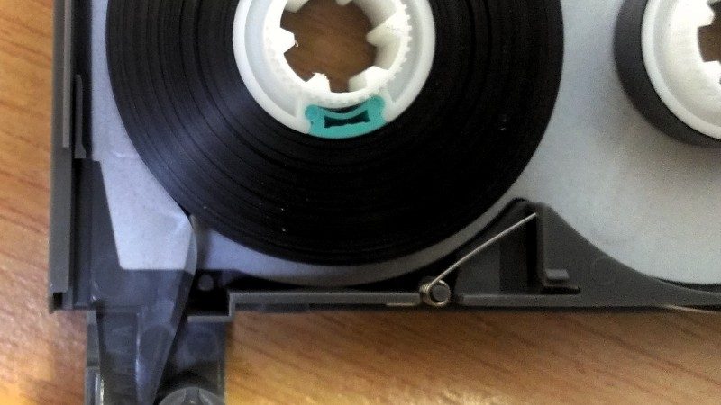
We’ve also started to see a particularly nasty problem with some, and usually the 120 minute length, DATs. The first symptoms are a broken DAT tape usually on wind. The tape pack seems to become slightly sticky, with intermittent tension between the layers of tape and with the thinner tape in 120 lengths this can sometimes break the tape on wind.
You can see in the above image how the tape sticks slightly to the pack and then releases when hand wound. With the greater tension of a machine wind and the tape also wound around the head drum this becomes risky.
With large transfer jobs checking each DAT by disassembly is a mammoth task, but the permanent damage and / or part loss of a section of audio caused by a break is not feasible either!
Contact us, of course! No seriously, how to transfer video to dvd or any other digital format is a very simple concept but the reality can be pretty complex. As with much mature technology, the domestic video formats and machines were often made pretty straightforward to use and hid much of the complexity of analogue video from us.
The simplest methods are to use the few machines ready made for the transfer purpose but these were only made for the most common video formats. Several manufacturers made VHS to DVD units and these can work well if MPEG2 DVD Video is the only format you require.
The problems come for the less common formats and when the tapes themselves start exhibiting physical problems.
Times are changing though and even the most common domestic formats like VHS will soon become harder to work with. While it’s still possible to buy older video machines that may work and your old video machine at home or in the attic may still work this situation is changing fairly quickly.
Very few manufacturers carry a full range of spares for their older machines anymore and often what stock they have, once sold is never remade. Even in the professional and broadcast markets companies like Sony only guarantee spares support for equipment up to 10 years from manufacture.
What this all means is that to support a range of legacy, analogue video formats as we do, constant sourcing of parts, parts machines, obsolete service manuals and older specialist knowledge is vital. This isn’t always easy or cheap and highlights one of the key issues in digitising video tape.
The Teac A3440 is a classic reel to reel tape recorder from the late 1970s, early ’80s significant in that you could use it to make 4 track multitrack recordings at 15 inches per second, the professional tape recording speed. At the time there was precious little else around at the price to do this so this machine was perfect for small bands and studios who didn’t have the wallet busting amounts needed to buy a larger format 16 or 24 track recorder.
While the A3440 isn’t the last word in high quality analogue recording it has had some significant users in the past none less than Lee Perry who’d used the earlier but similar A3340 on his Heart of the Congos album.
the problems
This machine didn’t initially look heavily used, the heads had little wear but it hadn’t been used in a long while and there was a heavy build up of tape residue on the whole tape path. The capstan was very dirty and in these cases xylene is a more effective cleaner than IPA but don’t get it anywhere near plastic!
This A3340 powered up but the right hand tension arm was hanging at an odd angle and it wouldn’t play or wind.
Time to take it apart – the fake wood sides and rear panels get removed and it’s pretty easy to see what one of the problems is.
A very nasty ‘melted’ rubber capstan belt that took a fair while to scrape and clean off with IPA.
A new belt has purchased online – Teac parts in the UK are a big pain to get hold of through the official channels and I’ve given up contacting them unless I’m desperate for a part I can’t find anywhere else.
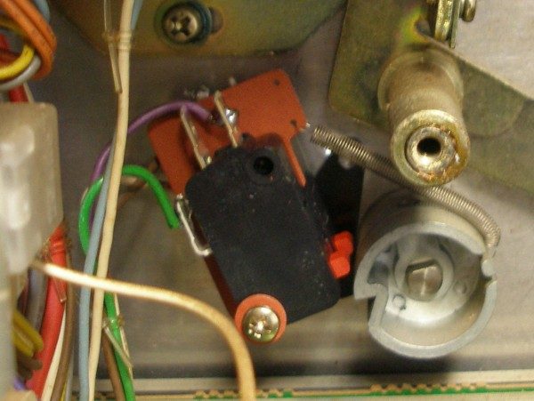
The other lack of drive was caused by broken micro switches. When the right hand tension arm is moved up, two micro switches behind the front panel switch power on for the capstan and reel motors. As this arm can get a los of use / abuse it’s common for the micro switches to crack. Both on this example were broken as was the small plastic piece that stops the arm moving too far down.
the repairs
To replace the capstan belt:-
Remove both screws holding the capstan flywheel against the front panel.
Make sure the flywheel is cleaned of all old belt debris.
Make sure the motor wheel is cleaned of all old belt debris.
Refit new belt over small motor wheel, then flywheel.
Replace bracket remove in part 1, making sure you’ve cleaned off the old grease and regreased where the end of the capstan shaft can run.
Although not essential I took the opportunity to remove the whole capstan shaft, clean, check for wear and reoil before putting back. If you do this you will need to reset the endfloat though.
microswitches
It’s not possible or worthwhile trying to repair the microswitches as the modern equivalent that fits perfectly is very cheap. Two were purchased from Farnell and replacement is just a case of:
Unscrew and move away the control PCB to get more space
Make a note of or photograph wiring connections for switches.
Unscrew and carefully desolder the existing microswitches.
Connect wires and solder the new switches in.
The arm end stop was repaired easily with strong super glue and after many hours is still holding.
is it working?
In a word, kind of! The belt and microswitches got the deck and transport moving. It will pull tape and make a noise which is great but an annoying intermittent problem started to appear after some initial testing.
When play or wind are selected, large solenoids clunk and release the reel brakes and move the pinch wheel. This was working BUT occassionally and only in play the right reel brake solenoid didn’t move, leaving the brake on, causing the tape speed to slow, back tension to increase and wow to go crazy!
We’ve been a bit quiet since last year on our blog here primarily because we have been processing a large, ongoing audio archiving digital migration job for Mood Media Ltd
In essence audio archiving, digital migration, transfer or digitisation, whatever term you prefer, is conceptually simple: one analogue or digital format is moved to another, usually digital, format. It is in the details of this process that things can get complex – requiring experience, specialised tools and often custom-built solutions.
This job has many factors – not just attaining the best analogue transfers, but also addressing the organisation of such a large amount of 10.5″ reels, their digital management once migrated and the creation and management of metadata.
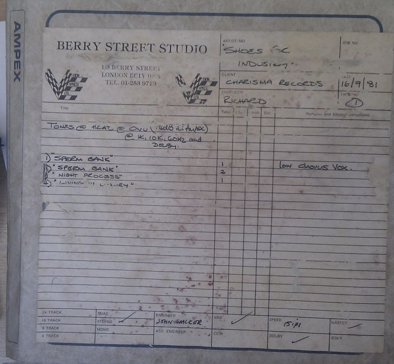
The archive, dating from the 1950s up to the early ’90s, even though it had been stored in less than ideal conditions, is in generally good condition. An interesting and often fantastic-sounding collection of recordings and music are evident all recorded at 15ips in mono, stereo and some encoded with Dolby A noise reduction.
There are specific issues with some tapes that are not uncommon with older audio tape:
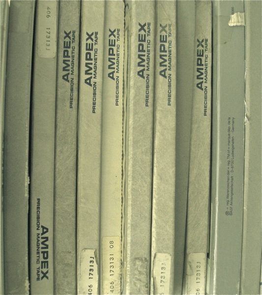
Binder hydrolysis or sticky shed syndrome (SSS) has affected a significant proportion of the archive in particular Ampex branded tapes from the 1980s onwards.
Some glue used in spices from the 1980s spreads over time and tends to stick layers of tape adjacent to the splice together. This can be a very frustrating problem which rarely damages the tape permanently, but affects the tape tension on certain sections so that head to tape contact is momentarily lost and a very obvious audio glitch noticed.
The analogue side is important to get correct initially but the management of the data is critical with such a large number of reels and individual artists and tracks. Each batch of tapes would be catalogued in a .csv file. The digital audio transfers were split into individual tracks which then had to be renamed based on the data in the .csv file. This was handled by some php coding which matched the metadata supplied with the files, checking for inconsistencies then renaming the .wav files on one of our servers.
This type of customised workflow can be tricky to setup initially and find the balance between accuracy and speed but once done a smooth workflow is possible maintaining high quality, accuracy and value.
Tascam, Fostex and Yamaha sold cassette multitrack recorders in the golden days of home recording in the 1980s and ’90s. The 4 track format was especially popular but an 8 track format was also developed that squeezed even more out of the small tape width of the cassette.
We love these cassette formats and their accessibility helped start many musicians’ careers. Unfortunately one of the best 8 track machines, the Tascam 238 Syncaset also suffers from a common and frustrating problem that renders most of these machines useless over time, the dreaded direct drive capstan motor failure…
The 238 and other 8 track and high quality stereo tape decks, the 688 and 122 MkII and III, used a direct drive capstan motor for precise speed control and reduced speed variation or wow and flutter (w/f). The circuit that controls this motor fails in certain ways causing lack of speed control and in our case the capstan motor wizzing away at a crazy speed, not the 9.5 cm/sec that it should do.
This here is the culprit – you can see the attempted repairs which didn’t ultimately work.
One common failure is that the surface mount electrolytic capacitors fail or their capacitance changes to such an extent to cause speed problems. These can be changed for standard through hole caps but you do need to be very careful as the tracks are damaged very easily – good tools are essential.
The other point of failure in the circuit is the BA6304F SO16 IC – we even changed this but the motor still didn’t turn!
There was some suggestion from previous repairers that the grease at the end of the capstan flywheel hardens over time. increasing the friction and causing problems with the circuit.
This can become frustrating quickly, especially when you have a large archive of cassettes to digitise.
When we can’t repair we reluctantly do the next best thing and buy the whole replacement part but this is another exercise in frustration. Teac parts and Teac UK don’t have any european supply of this capstan motor (part no. 53700075-01) anymore as of November 2011. Interestingly about 6 months ago they did at around £60 GBP, then about 3 months ago they had one left at £160 GBP!
Lots of emails later to Teac US, Teac Canada and Teac Japan there seem to be a nice stock still on shelves somewhere and at reasonable prices UNTIL you ask them to ship to the UK when you discover they can’t do this and I’d need to go through Teac UK!!! I’m pretty persistent but I gave up finally even though some of the support staff tried to be pretty helpful.
We find support for older machines from the original manufacturers is not good generally and unreasonably expensive when you can find it. This is similar across audio and video, semi-pro and professional products. Some companies are easier to deal with and have a better parts situation than others, but stockpiling machines, parts, manuals and obsolete knowledge is the best course of action.
What we finally did that worked and was a good solution was purchase 3 Tascam 122 Mk III stereo cassette decks which use the same but a later revision of the capstan motor, (part no. 53700121-00).
One machine was donated for the cause and the capstan motor removed, modified and refitted in the 238. The 122 motor has a few factory extras, such as these resistors, shown here:
You also need to solder / desolder the speed pads, to change the motor speed from 4.8 cm/s to 9.6 cm/s that the 238 needs to run at.
It’s also a good idea once you’ve got the capstan motor apart to clean the old grease from the seat, check the end float which can be adjusted using the screw shown on the left and apply new grease to the capstan end.
Put it all back together – be careful to solder the wires to the motor to the correct pads – they’re different on the 122 and test… Ours worked almost perfectly.
As the transport hadn’t been used for a while the reel motor would intermittently stop as if sensing the tape end. This can sometimes be loose counter belts but on the 238 it’s a digitial counter. We cleaned up the leaf switches on the transport top and also sprayed a small amount of deoxit into the inside of the reel motor. A bit more use and it finally worked to spec…
Digital formats are great and the ease of access and distribution that an Audio CD and a Video DVD offers is fantastic at the moment with cheap players, recorders and personal computers. In the audio and video tape transfer business, getting your business website to rank well in the search engines for key phrases such as ‘copy tape to cd’ or ‘convert video to dvd’ should get you a steady stream of enquiries from people who, primarily, can’t access their tapes any more. The preservation of the valuable recording is usually perceived to be CD or the DVD.
My concerns with the ‘…to CD’ and ‘…to DVD’ process are:
Optical Media that can be burnt using computers, CDr and DVDr, are not as reliable as commercially produced or ‘stamped’ discs and their quality and longevity can vary between different manufacturers.
The digital video stored on a DVD Video is a lossy compressed format that depending on the original footage and if pushed for too much running time can easily make the digital transfer look much worse than the original – not a good reason to transfer the tape!
The everyday nature of audio and video discs and some of the domestic technology we now have has conspired to make what is and can be a complex, time consuming and often problematic process too simple in the eyes of many people.
Since the early marketing of the compact disc in the ’80s by spreading jam on it to highlight its resilience compared to vinyl or tape, many of us have been taken in by this and have a skewed belief on the longevity of CD and DVD optical media. In fact optical media can degrade and become unreadable and unplayable in a very short space of time even with good storage practices. Tape based storage formats of course have their numerous problems but they can often be incredibly resilient over time even in under poor storage conditions. When tape does degrade it is rare event when it cannot be treated and made playable .
CDr and DVDr Longevity
Optical media that can be burnt form CD / DVD writers uses a dye that the laser alters to create pits that are read back as digital data. CD and DVDr discs use different dyes due to the different data storage needs. The dye can be affected by bright sunlight and compared to commercial or ‘stamped’ optical media it is not as reliable.
It has been speculated that the archival quality of CD is superior to that of DVD. The basis for this lay with the physical differences in CD and DVD optical media and the maturity of the technology. In particular, the size of the bit markings in CD media not only reduces the relative effect of media or dye degradation, but also means that more stable, less sensitive dye may be used.
Out with old, in with the new
The march of technology can cost us money while making huge profits too. This of the CD reissues of old back catalogue albums, the pressure to replace vinyl collections with CDs, video tape collections with DVDs or CRT televisions with LCD or plasma screens. New technology is marketed as ‘better’ in many ways, yet it can be worse too.
One of our audio and video archive customers has a large collection of AVCHD video files that are stored in 1.9GB ‘chunks’ as xxxxx.MTS files. All these files are of 60 minute and longer duration and must be joined, deinterlaced, re encoded to a suitable size and bitrate then uploaded for online access.
This is quite a task in computer time and file handling. These small domestic cameras produce good HD movies for a low cost but the compression to achieve this is very high and does not give you a file that is easily edited. The .MTS files are MPEG transport stream containers for H264 encoded video.
There are some proprietary solutions for MacOS X and Windows that will repackage the .MTS files into .MOV Quicktime containers that can be accessed by MacOS X or re-encoded to a less compressed format for editing with Final Cut Pro or Premiere. We didn’t need this though, just a reliable and quick open source workflow.
The first and most important issue is to rejoin the camera split files.
These cameras use FAT32 file systems which cannot handle individual files larger than 2GB so they split the .MTS video file into chunks. As each chunk in a continuous sequence references the other chunks these must be joined in the correct order. This is easily achieved with the cat command.
The rejoined .MTS files can now be reencoded to a more manageable size using open source software such as Handbrake. We also needed to deinterlace our footage as it was shot interlaced and it would be accessed on progressive displays. This will increase the encoding time but without it any movement will look odd with visible artifacts.
Finding the ‘sweet spot’ for encoding can be time consuming but in this case was important as projected text needed to be legible but the file sizes kept manageable for reasonable upload times!
Cassette tapes run at a very slow speed of 17⁄8 inches per second (ips) with a very small track width of 1.59mm
Cassette decks when they left the factory or a service centre should have been aligned to a standard reference for the position of the record and play heads. Unfortunately they often weren’t all the same and over time the alignment can drift, get knocked out or manually ‘fiddled with’ by an owner.
What this means is that unless you’re playing back your tape on the machine it was originally recorded on, you may not be getting the maximum quality as the angle of the head to the recording or azimuth will not be optimal.
Without calibration tones recorded at the start of the tape (which is very unlikely on most domestic cassette tape recordings), you must set the playback azimuth manually. A few high end tape decks, namely those made by Nakamichi, either had a easily accessed Azimuth Adjust or could even automatically adjust this throughout the tape. The Nakamichi Dragon was one such tape deck and could be the best, if working well, for high quality playback.
If you want to transfer or convert a cassette to CD and adjust the azimuth yourself this is the easy way to do it:
Look at the tape path (everything the tape will move across) and if it looks brown and dirty get some isopropyl alcohol and give it a good clean with a cotton bud.
If you haven’t demagnetised your deck for a while now would be a good time to do it..
Power up your cassette deck, which hopefully works correctly and doesn’t have too much speed instability!
Pop your tape in the cassette well and start to play.
Turn your amplifier’s volume up and if you can put it in Mono.
Now, look under the tape machine’s playback or combined record and playback heads you should see a small screw or nut possibly with anti tamper paint on it.
Using an appropriate tool, turn this nut or screw a little left or right while listening to the audio.
You should hear the recording, especially if it has a lot of high frequency content such as cymbals etc. get bright and dull sounding or more technically get more in or out of phase.
Your aim is to get the most in phase or bright sounding playback.
Sounds better now?? Great, start to record using you favourite computer audio software. We like SoX for the control but there’s a huge range out there.
We often get sent Digital Audio Tapes or DATs for transfer to .WAV computer files. As these recordings are already digital or ‘born digital’ the process should be straightforward. Our audio interface cards accept the SPDIF or AES digital audio stream from the DAT machine and record this as a WAV or BWAV file. This file can then be burnt as a CD or delivered digitally on a hard drive or removable media.
The big problems though come with the tape that these digital recordings are made on. The tape is only 3.81 mm wide and moves at a very slow 8.15 mm/sec. The tape is also very thin at 13 microns. The recording system and transport used is helical scan just like in video recording but with the very slow tape speed and small tape dimensions any defects or problems with the tape can result in many errors which may not be correctable by the error-correcting system of the DAT machine.
One problem we’re starting to see more and more are tapes that snap. The tape pictured above was a D120 which was never recommended by the DAT machine manufacturers but was still often used for its extended recording time. This tape snapped without warning a quarter of the way through the recording. There were no outward signs or potential problems just a sudden clean break on a diagonal.
To recover this tape it could have been spliced with splicing tape of the correct width like in analogue recording but there is a high risk if not done perfectly of irreparable damage to heads on the drum. Even with this type of repair some of the material would have been lost. A safer solution is to rehouse each spool in another shell. This lets you recover as much as possible from the tape, without the risk of head damage.
Whichever solution you decide, the DAT shell must be disassembled. A small crosshead screwdriver needs to be used to remove all the case screws. There are two hidden ones, accessed by sliding part of the cassette shell down:
You can now carefully lift both halves of the DAT shell apart, making a note of the tape path inside the shell. Be careful not to touch the tape with your bare skin as fingermarks and grease can cause head to tape contact problems and audio errors and dropouts.
We have several of these large, wonderful machines. It’s not often we need or want to get involved in DAT machine repair as generally they are not easy to service machines and many key transport parts are becoming unavailable. The Sony 7030 DAT though has been designed with easy servicing in mind. There’s alot of room in these things and each section is clearly marked and separated into distinct boards much like Sony Broadcast video machines.
These are timecode DAT machines and were once common in video post production houses and the more well funded recording studios. The problem with some of this well built kit though is exactly that it works too well and gets left on for long periods through it’s life and this can take a toll on certain components, especially electrolytic capacitors. Heat builds up in electronic circuits, especially in switch mode power supplies that larger broadcast items often use. Capacitors have a rated life at 85°C or 105°C at several thousand hours. With hotter environments, substandard parts and long operating hours these capacitors can soon outlive their original design life.
Our 7030 DAT had started behaving oddly and at first the display would flash on and off after a short while powered on. Another machine would power up for 30 secs then just die. Before delving into the enormous service volumes it’s always worth replacing the Switch Mode Power Supplies (SMPS). These like many broadcast machines use supplies that are sometimes generic made by other companies and which can be bought at Farnell or RS. We did it the harder way and desoldered all the old capacitors in the power supply and replaced these with high quality low ESR Panasonic ones which should give us another 6000 hours of running time. So far this machine has worked perfectly although you do need good soldering and desoldering technique on these boards. A powered air desoldering station is a good idea, much, much better than a hand solder pump.
Like much late 1970s and ’80s studio recordings, this was recorded on Ampex branded tape that suffers badly from binder hydrolysis or ‘sticky shed syndrome’ that must be addressed before the tape can be successfully played and digitised. This was in addition to the mould growth that was evident on the tape pack edges, and cardboard box. Storage in damp conditions and high humidity causes this type of mould and increases the breakdown of magnetic tape generally, sometimes to the point where de-lamination occurs, that is, the binder breaks away from the polyester structure of the tape. When this happens, which is luckily quite rarely, the magnetic information is damaged and mostly lost beyond repair.
Thankfully this tape, whilst it looked in poor condition was relatively straightforward to restore but time consuming. Careful hand winding, and mould cleaning is necessary as is awareness of the potential health effects of some mould spores so good ventilation and protective masks are necessary.
We have recently worked on probably the worst looking tapes but with some of the best sounding music recordings we’ve seen for a while! A batch of 10.5″ NAB studio masters had bad tape mould growth.
Andy Leighton, owner of Bolex Brothers and music publisher of the Rocky Horror Show, found a batch of studio masters on quarter inch tape that had been growing mould for some of them over 30 years. All of these recordings had been made at the renowned Sound and Recording Mobile studios better known as SARM, later creative home of Trevor Horn.
Among these tapes was the first ever recording made at SARM in 1972 by Richard o’Brien, writer of the Rocky Horror Show, in addition to rare tracks by artists such as Kimi and Ritz.
When the tape mould was finally cleaned from the tapes and some of them baked for binder hydrolysis the quality of the recordings was very high and testament to the high quality available from analogue recording. Even though tape can be vulnerable to physical problems, it is also robust. If these had been tape-based digital recordings, in the same condition, I doubt we’d have been able to achieve the same results.
We were contacted recently by Jack Hawkins, the renowned arranger and band leader to consult on and digitise personal quarter inch open reel recordings of his band.
In case you don’t know, The Jack Hawkins band are probably best known for their performance of the track 30-60-90 made famous in a club sequence in the 1971 film Get Carter starring Michael Caine.
Once a common sight in Radio stations around the world, the NAB Cartridge machine or Fidelipac was used for short jingles and announcements, sometimes even for longer recordings. Using a similar sized cartridge to a domestic 8 track machine the NAB cartridge was different in that the pinch roller was not in the cartridge but would hinge up in the player and hold the tape against the capstan. Running at 7.5 inches per second (ips) compared to 3.75 ips in domestic cart machines the recording and reproduction quality good be very good but it was the ease of use and cueing ability offered by these machines that made them so useful in broadcasting.
We have Sonifex cart machines that while very well built do have rubber parts that will degrade over time and reduce the transport performance. Luckily we have some of the last remaining stock of new pinch rollers, motors and capstan drive belts.
The pinch roller in one of our machines had become quite hard and the rubber shiney over time. A pinch roller in this state may not hold the tape as securely and could also have flat spots both leading to increased wow and flutter and poor tape handling. These pinch rollers also have high quality cartridge bearings pressed into their shell. Over time these loose their lubrication, wear, become rough feeling and will also add to poor tape handling.
Older, fragile and valuable tape must be handled and used carefully. A ‘chewed’ tape caused by a poorly maintained tape transport in any tape machine, audio or video is a disaster and hard to recover from perfectly.
Both halves of the cart machine case need to be removed to easily change the pinch roller. While the access is good and the machine, in this case a Sonifex microHS, had been designed for easy servicing the pinch roller is still a little fiddly to get to so I removed the transport from the main chassis.
To remove the pinch roller a small slightly hidden C clip must be removed you can see in the image above the slot machined into the roller shaft where it sits and holds the roller. This is hard to remove as the plastic bush on top of the roller stops you getting a small screwdriver in. I managed to remove the C clip with some fine circlip pliers. Be careful not to loose the clip if you don’t have spares, they fly away very easily!
Now the new roller can be placed on the shaft. It’s a good idea once all the transport is out to give everything a good clean with IPA.
On this machine, the castan drive belt was quite slack so a new one was fitted, which is easy now the transport is removed. First though the capstan flywheel and motor pulley were cleaned of all the old rubber belt residue that tends to accumulate over time.
The last thing to do is check the pinch roller pressure. This is important to as to high or too low will increase wow and flutter, increase wear to the bearings and capstan surface and give poor tape handling. Due to the design of these NAB cart machines, the pinch pressure needs to be checked with a special cartridge. The pinch pressure is then adjusted from a screw pot on the top PCB seen outlined below in green.
Celebrate What? is a documentary we transferred and created DVD access copies for its director recently. He only had a VHS copy of the 8mm original unfortunately but it’s still a great piece of history about St Pauls, the St Pauls Carnival and Bristol.
If anyone can recognise themselves or anyone else, please contact the director, Colin Thomas by email, ctbr03509 at blueyonder.co.uk
2 U-matic video tapes were discovered of a Black Roots live performance in Bristol in the 1980s. We were able to restore, digitise and make the umatic transfer of this recording as a high quality, uncompressed Quicktime file then encode and author a DVD for future release by Bristol Archive Records.
Some information supplied by the label:
Black Roots were Bristol’s premier Reggae band throughout the eighties and having gone their separate ways in the nineties they reformed last year and will be rekindling the magic with an intimate hometown gig at the Fleece on Friday September 9th, the show coincides with the release of “Black Roots – The Reggae Singles Anthology”, released on Bristol Archive Records in collaboration with Nubian Records, this release showcases all of the band’s singles released during their first decade and as an extra bonus the CD issue comes coupled with a DVD of the band’s 1986 video release “Celebration” recorded at the long gone Studio nightclub in Bristol. This show will be something special and likely sell out so book your tickets early and don’t miss out.
We were very excited recently when Chris Bradfield from Soundscommercial uncovered a previously unseen batch of EIAJ half inch reel to reel video tapes. In the process of looking for 1976 footage for their event, Spirit of 76, we uncovered many other gems. One of these goals was the famous hat-trick scored by Kevin Mabbutt against Manchester United at Old Trafford in 1978. Mabbutt is one of only two players in Football League history even to have done this and this footage was never recorded anywhere else!
Unfortunately this large batch of valuable recordings had been stored in damp, unheated conditions and had suffered. The tape had deteriorated in several ways.
Mould growth was evident on some tapes
The oldest tapes from the early 1970s were shedding oxide severely and had little lubrication left in the binder.
Binder hydrolysis, often called sticky shed was evident on other tapes.
Each issue needed a different process to treat the tape. The common assumption that ‘tape baking‘ will restore all unplayable tape is not true. It is just one solution to one of these issues and can cause more problems if used incorrectly. Deteriorated video tape is much less forgiving than audio tape when attempting transfer and must always be handled and processed with extreme care. Crinkled, curled, edge damaged tapes are next to impossible to restore back to their original condition and it’s common that more damage can occur when owners are desperate to transfer footage.
We were able to restore all the tapes to a playable condition and make uncompressed quicktime files of these.
Below is a clip from a later recording. We are not able, unfortunately, to show the Kevin Mabbutt clip yet.